
A strip steel burr grinding device and debugging method for a finishing unit

A technology of finishing unit and debugging method, which is applied to machine tools suitable for grinding workpiece edges, parts of grinding machine tools, grinding machines, etc., can solve the problems of large space occupation, cumbersomeness, and single targeted design of grinding devices. , to achieve the effect of solving burr defects and improving quality

Active Publication Date: 2018-09-04
BAOSHAN IRON & STEEL CO LTD
View PDF5 Cites 0 Cited by
  • Summary
  • Abstract
  • Description
  • Claims
  • Application Information

AI Technical Summary

Problems solved by technology

[0006] 1. The strip steel burr grinding device and other equipment occupy a large space and are heavy, and adding it to the unit will often cause interference with other equipment;
[0007] 2. The grinding effect is not obvious;
[0008] 3. Due to the interference of equipment such as the strip steel burr grinding device and the unit process, new production problems have been introduced;
[0009] 4. For different strips, it is necessary to comprehensively adjust the grinding height, grinding angle and grinding force to ensure the final grinding quality. However, most of the existing burr grinding devices cannot flexibly adjust the grinding height and angle. and adjustment of grinding force;
[0010] 5. The specific design of some grinding devices is too single, and it is difficult to adapt to the change of strip specifications

Method used


Image

  • A strip steel burr grinding device and debugging method for a finishing unit
  • A strip steel burr grinding device and debugging method for a finishing unit
  • A strip steel burr grinding device and debugging method for a finishing unit

Examples


Embodiment

[0119] In order to further illustrate the application process of the technology of the present invention, taking a process section of a finishing unit as an example, the debugging process and application effect of the unit applying the present invention are introduced in detail.

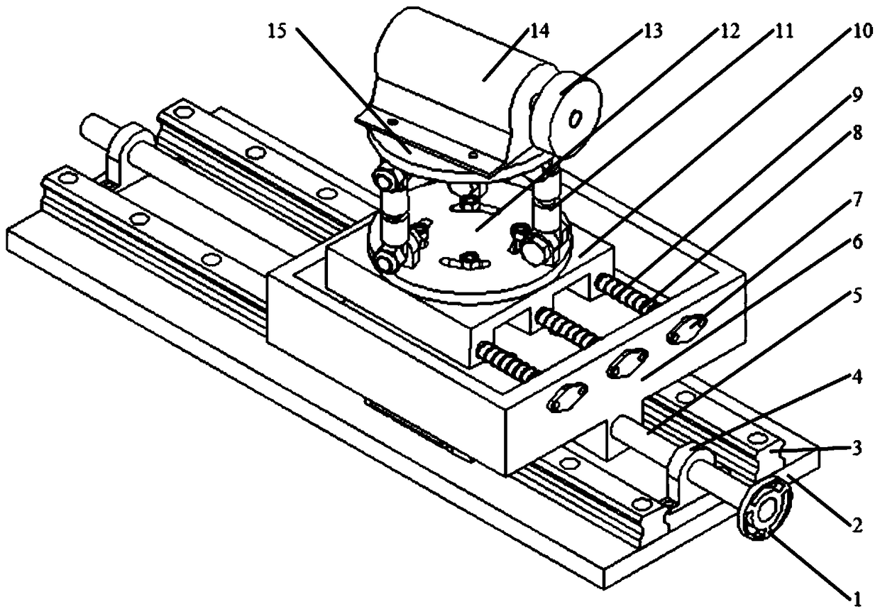
[0120] A strip steel burr grinding device for a finishing unit, comprising a horizontal feed mechanism, a horizontal angle adjustment and locking mechanism, a vertical angle adjustment and locking mechanism, and is arranged on the vertical angle adjustment and locking mechanism, The grinding wheel is used for grinding the strip burrs, and the strip steel burr grinding device is used to adjust the setting direction, inclination angle, direction, contact position, grinding pressure, etc. of the grinding wheel relative to the strip.

[0121] The transverse feed mechanism is used to enable the strip steel burr grinding device to run along the track, so that the grinding wheel can adapt to the change of st...


PUM


Abstract

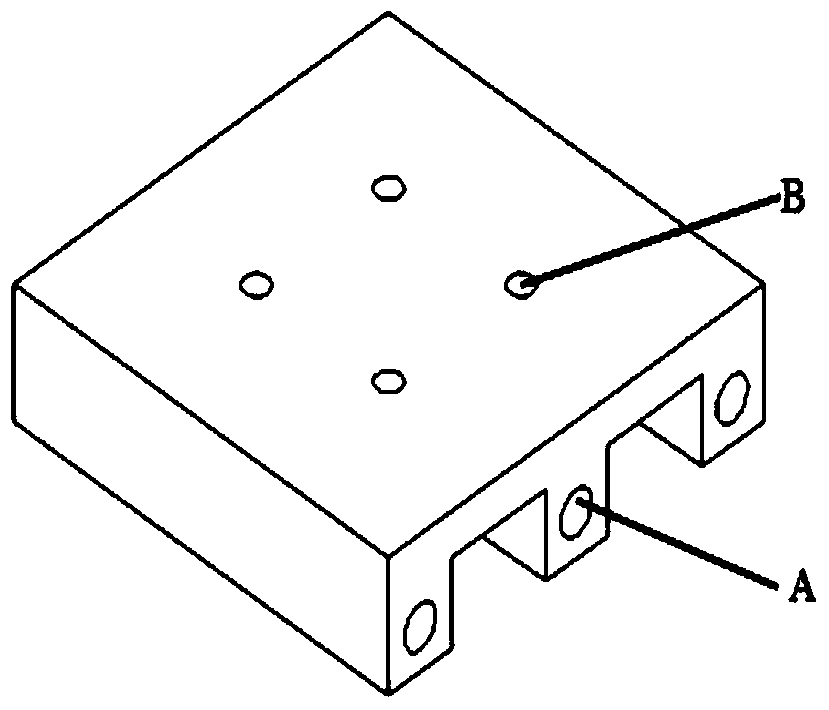
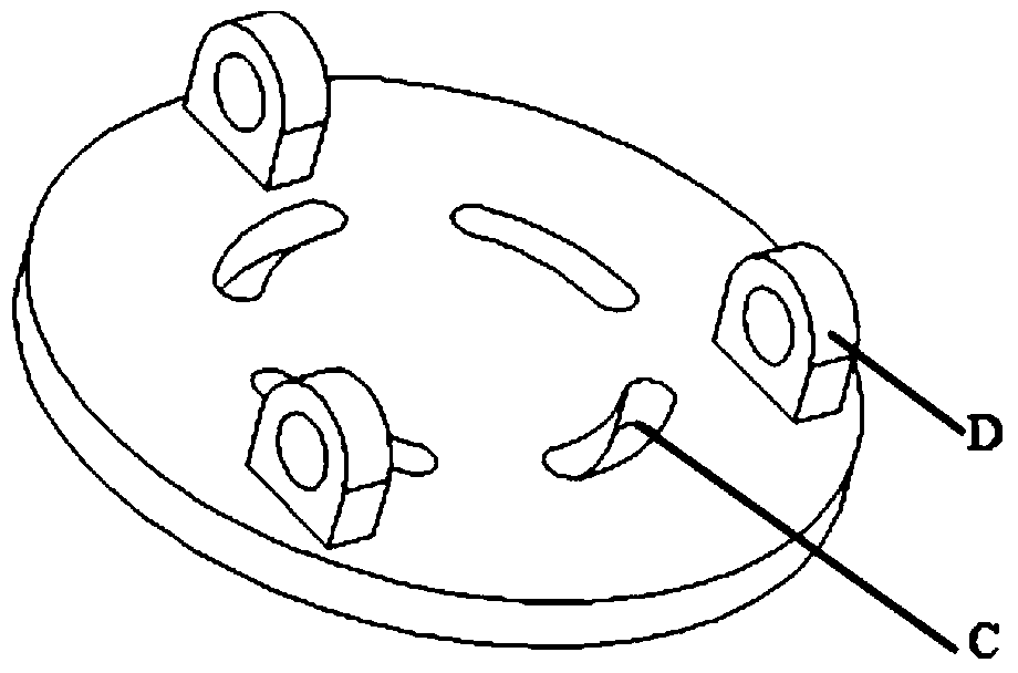
The invention discloses a strip steel burr polishing device applied to a finishing unit. The strip steel burr polishing device comprises a horizontal feeding mechanism, a horizontal angle adjusting and locking mechanism and a vertical angle adjusting mechanism, wherein the horizontal feeding mechanism is used for allowing the strip steel burr polishing device to run along a track so as to adapt to changes of specification of strip steel; the horizontal angle adjusting and locking mechanism is arranged on the horizontal feeding mechanism and comprises a motor lower base (10) and a motor middle base (12), wherein the motor lower base (10) and the motor middle base (12) are connected by a bolt; the motor lower base (10) and the motor middle base (12) are provided with waist-shaped hole sliding chutes and a bolt structure, wherein the waist-shaped sliding chutes are used for relative horizontal rotation of the motor lower base (10) and the motor middle base (12), and the bolt structure is used for fixation, and thus adjustment of horizontal angle of the device is implemented; the vertical angle adjusting mechanism is arranged on the motor middle base (12) of the horizontal angle adjusting and locking mechanism and is used for adjusting the height and the vertical angle of the burr polishing device. The burr polishing device disclosed by the invention is ingeniously adjustable in feeding, adjustable in horizontal angle, adjustable in vertical angle, adjustable in height, adjustable in burr polishing pressure and capable of adapting to different burr polishing requirements of different specifications and different steel types.

Description

technical field [0001] The invention relates to the field of metallurgical finishing, in particular, the invention relates to a strip steel burr grinding device for a finishing unit and a debugging method thereof. Background technique [0002] So far, in order to meet the requirements of different users for the strip width, a strip trimming device—disc shears is installed in the finishing unit to perform edge-holding treatment on the strip after the disc has trimmed the edge. [0003] However, due to its own equipment characteristics, disc shears will also cause burrs to appear on the edge of the strip during processing. Generally speaking, in the finishing unit, the deburring machine will also be used to press the strip steel after the disc has been sheared. The working principle of the deburring machine is to use a roller with a certain roll shape or Wheels, extruding the edges of the strip. However, in fact, because the deburring machine only "presses down" the burrs, b...

Claims


Application Information

Patent Timeline
Patent Type & Authority Patents(China)
IPC IPC(8): B24B9/04B24B41/00
CPCB24B9/04B24B41/00
Inventor 马耿魏杨大华张博林顾利钟孙全社宋建勋
Owner BAOSHAN IRON & STEEL CO LTD
Learn More