Method and device for separating brittle transmissive materials with opposite-beam multi-focus laser

A multi-focus, opposite-beam technology, applied in the direction of laser welding equipment, metal processing equipment, welding equipment, etc., can solve the ideal design of laser multi-focus position and focus energy distribution, affect the thickness and quality of cutting and separating materials, Problems such as large differences in laser focus energy distribution, etc., to achieve high-quality and safe cutting separation, large practical use value, and the effect of improving cutting quality

Active Publication Date: 2018-04-24
HUAZHONG UNIV OF SCI & TECH
View PDF8 Cites 0 Cited by
  • Summary
  • Abstract
  • Description
  • Claims
  • Application Information

AI Technical Summary

Problems solved by technology

However, most of the existing multi-focus laser separation adopts the reflective focusing method to generate multi-focus laser (such as Chinese invention patent ZL201210118371.0). During the process of continuous reflection and propagation of the laser, the laser energy is continuously lost due to divergence, resulting in The number of laser focuses is small, and the energy distribution of each laser focus is quite different. Although the stress generated along the thickness direction has improved, there is still unevenness, and the unevenness becomes more serious as the thickness of the material increases. Therefore, laser cutting separation Material thickness is still limited
In addition, due to the inherent defects of the design method of this method of reflective focusing to generate multi-focus, the position of laser multi-focus generation and the energy distribution of the focus cannot be carried out according to the optimal design, which affects the thickness and quality of cutting and separating materials.

Method used


Image

  • Method and device for separating brittle transmissive materials with opposite-beam multi-focus laser
  • Method and device for separating brittle transmissive materials with opposite-beam multi-focus laser
  • Method and device for separating brittle transmissive materials with opposite-beam multi-focus laser

Examples


specific Embodiment approach

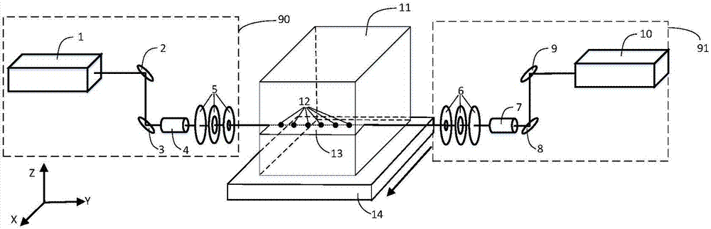
[0026] The technical solution provided by the present invention can be completed by one implementation mode, and there are two specific implementation modes for the composition and optical path of the multi-focal lens group. The specific implementation method comprises the following steps:

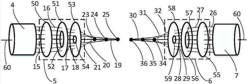
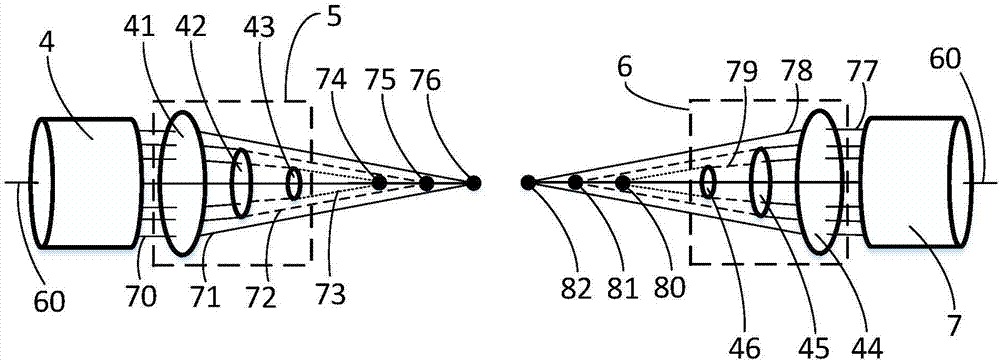
[0027] (1) A series of focusing lenses with small holes in the center or different diameters are combined to form two sets of multi-focus lens groups. Wherein, the number, focal length, aperture diameter or focusing lens diameter of each focusing lens is determined by parameters such as the thickness, absorption rate, and refractive index of the cut brittle transmission material. Adjust the distance between each focusing lens to make the focus position of the generated laser moderate.

[0028] (2) The first laser processing system is composed of the laser, the light guide mirror and the beam expander, and the multi-focus lens group is placed in front of the first laser processing system s...

example 1

[0040]Two YLM-150 fiber lasers are used as the first and second lasers, with an output wavelength of 1070nm and a maximum output power of 150W. The cutting material is KDP optical crystal, and the cutting size is 150mm×150mm×150mm. One conventional focusing lens and two focusing lenses with different diameters are used to form two sets of identical lens groups. After each laser beam passes through the lens group, three laser focal points will be generated. The distance between the laser focal points is 20mm, and the energy of the laser The proportions of the distribution (laser focal points are arranged sequentially along the laser transmission direction) are 30%, 30%, and 40%. The two sets of laser processing systems generate a total of 6 laser focal points, and the center distance between the two sets of laser focal points generated by the two sets of laser processing is 20mm. Experimental method: The first and second laser processing systems emit light at the same time, ad...

example 2

[0042] Two SD-YAG-600W Nd:YAG lasers are used as the first and second lasers, with an output wavelength of 1064nm and a maximum output power of 600W. The cutting material is quartz material, and the cutting size is 200mm×200mm×200mm. One conventional focusing lens and two focusing lenses with a small hole in the center are used to form two sets of identical lens groups. After each laser beam passes through the lens group, three laser focal points will be generated. The distance between the laser focal points is 30mm, and the laser The proportions of energy distribution (laser focal points arranged in sequence along the laser transmission direction) are 30%, 30%, and 40%. The two sets of laser processing systems generate a total of 6 laser focal points, and the center distance between the two sets of laser focal points generated by the two sets of laser processing is 20mm. Experimental method: The first and second laser processing systems emit light at the same time, and the o...


PUM


Abstract

The invention discloses a method and a device for correlative multi-focus laser separation of a fragile transmission material. The method is characterized in that the same technological parameters are adopted, and coaxial laser is utilized to penetrate multi-focus lens groups and to conduct inverse correlation on two sides in the thickness direction of the fragile transmission material to be separated, so that the number of focuses generated in the fragile transmission material is doubled to improve the laser energy absorption uniformity of the fragile transmission material in the thickness direction and to enhance the heating expansion uniformity of the fragile transmission material in the thickness direction. After a laser multi-focus beam leaves, the fragile transmission material is quickly cooled down in the thickness direction to produce tensile stress, so that separation of the thick fragile transmission material is realized by laser. The device comprises two sets of multi-focus laser processing systems and one three-dimensional working platform, wherein each set of the multi-focus laser processing system comprises a laser, light guiding mirrors, a beam expanding mirror and a multi-focus lens group. The method and the device realize high-quality, efficient and high-success-ratio separation of the thick fragile transmission material.

Description

technical field [0001] The invention belongs to the technical field of laser processing applications, and in particular relates to a method and device for separating brittle transmission materials by a through-beam multi-focus laser. The method is especially suitable for the separation of thick and brittle transmission materials such as KDP optical crystals. technical background [0002] Laser thermal cracking is currently an effective method for cutting and separating brittle transmission materials (such as glass, optical glass, optical crystal, etc.) to obtain high-quality separation edges. This method uses a laser focusing mirror to focus the laser beam on the surface or inside of a transparent material, and uses the high absorption rate of a certain band of laser light (such as a laser beam in the 10.6 μm band) of a brittle transmission material to form a surface to absorb laser energy, making the brittle transmission material Heating the surface of the material; or usin...

Claims


Application Information

Patent Timeline
Patent Type & Authority Patents(China)
IPC IPC(8): B23K26/38B23K26/067
CPCB23K26/0676B23K26/38
Inventor 段军刘朋邓磊敏曾晓雁
Owner HUAZHONG UNIV OF SCI & TECH
Why Eureka
Try Eureka