
Hybrid excitation Motor

A hybrid excitation motor, permanent magnet technology, applied in the direction of motors, electric vehicles, synchronous machine parts, etc., can solve the problems of increased maintenance work and reduced reliability of motor operation, and achieves improved reliability, improved reliability, and magnetic resistance. small effect

Active Publication Date: 2017-02-08
HUAZHONG UNIV OF SCI & TECH
View PDF11 Cites 33 Cited by
  • Summary
  • Abstract
  • Description
  • Claims
  • Application Information

AI Technical Summary

Problems solved by technology

[0005] However, since the excitation windings in the parallel hybrid excitation motor are all on the rotor, slip rings and brushes are required to feed DC current to the excitation windings, which will inevitably bring about problems such as electric sparks, which will reduce the reliability of the motor operation and require maintenance work. Increase

Method used


Image

  • Hybrid excitation Motor
  • Hybrid excitation Motor
  • Hybrid excitation Motor

Examples


Embodiment Construction

[0034] In order to make the object, technical solution and effect of the present invention clearer, the present invention will be described in further detail below in conjunction with the accompanying drawings and specific examples. The following examples are only used to explain the present invention and do not constitute a limitation to the present invention. In addition, the technical features involved in the various embodiments of the present invention described below can be combined with each other as long as they do not constitute a conflict with each other.

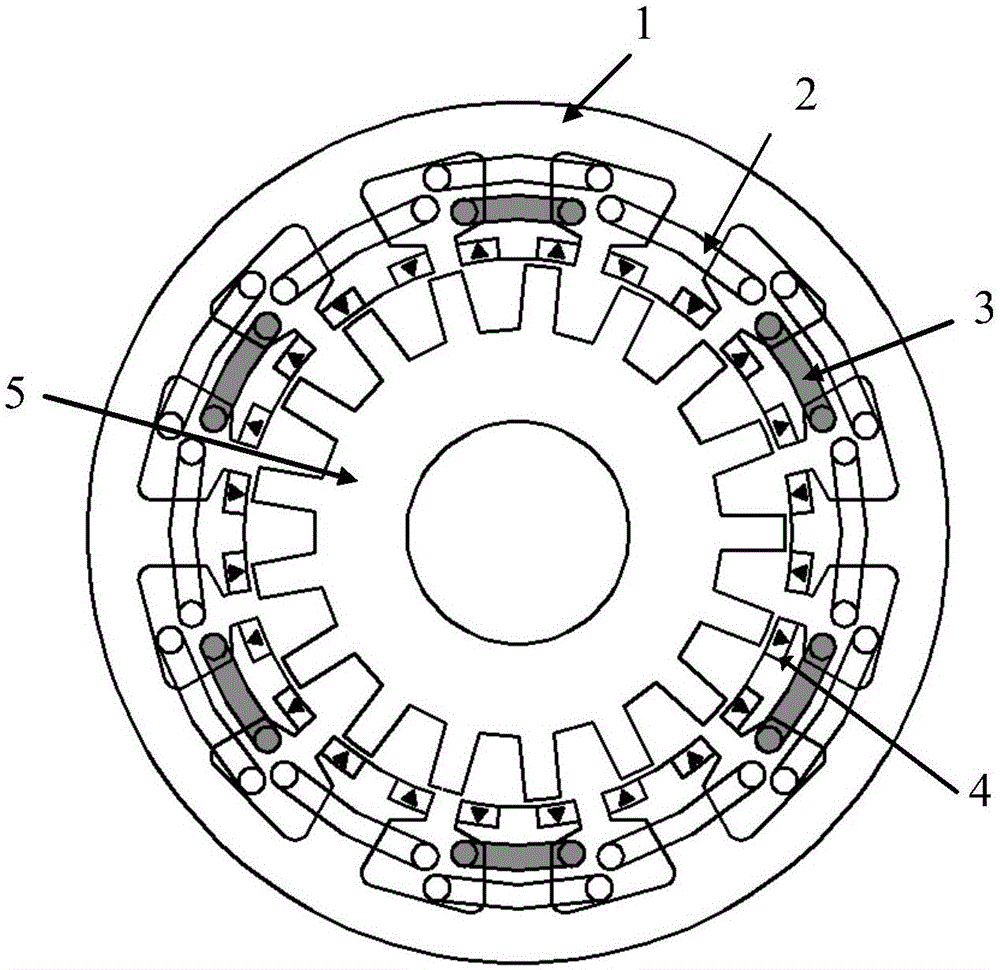
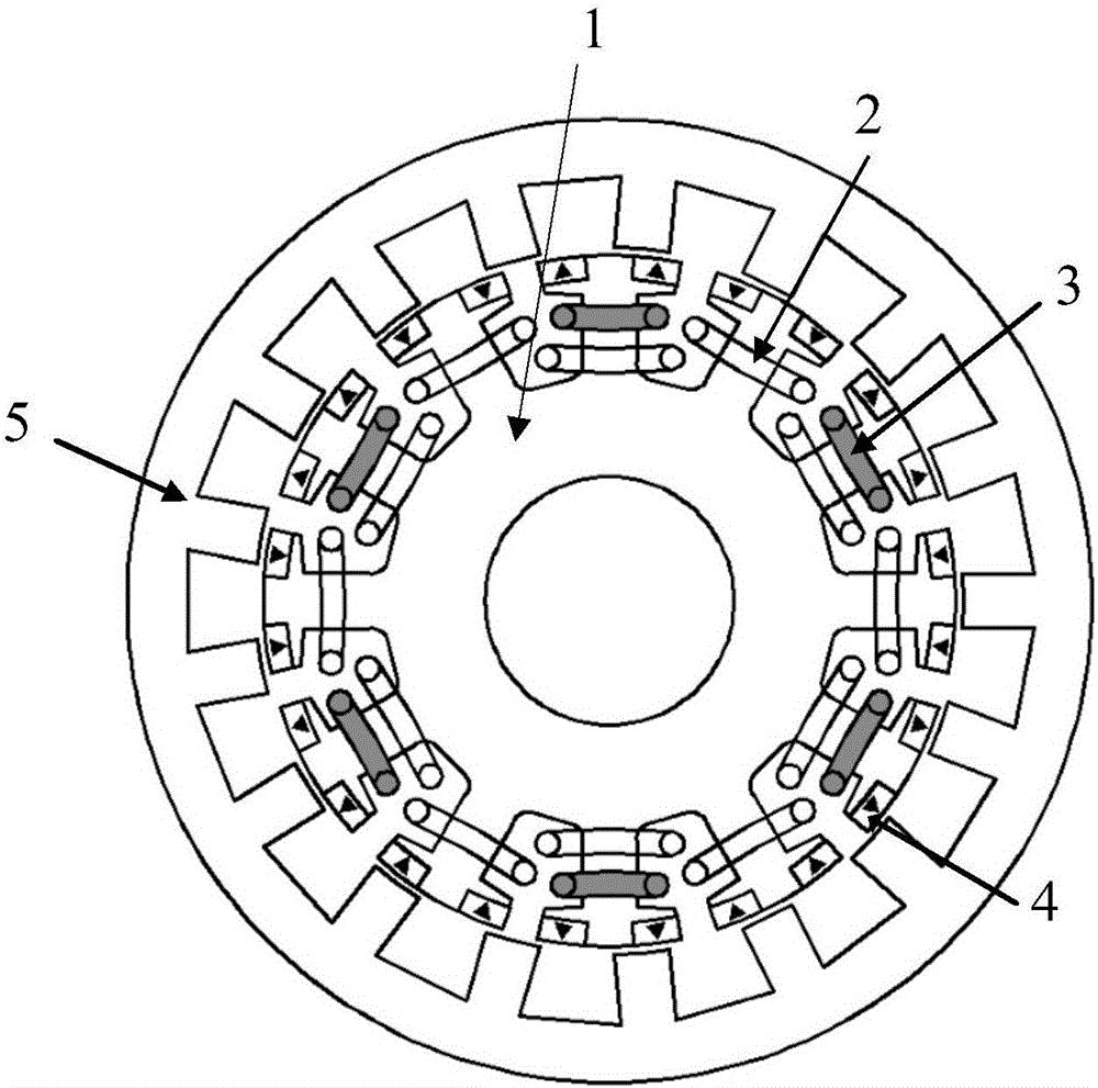
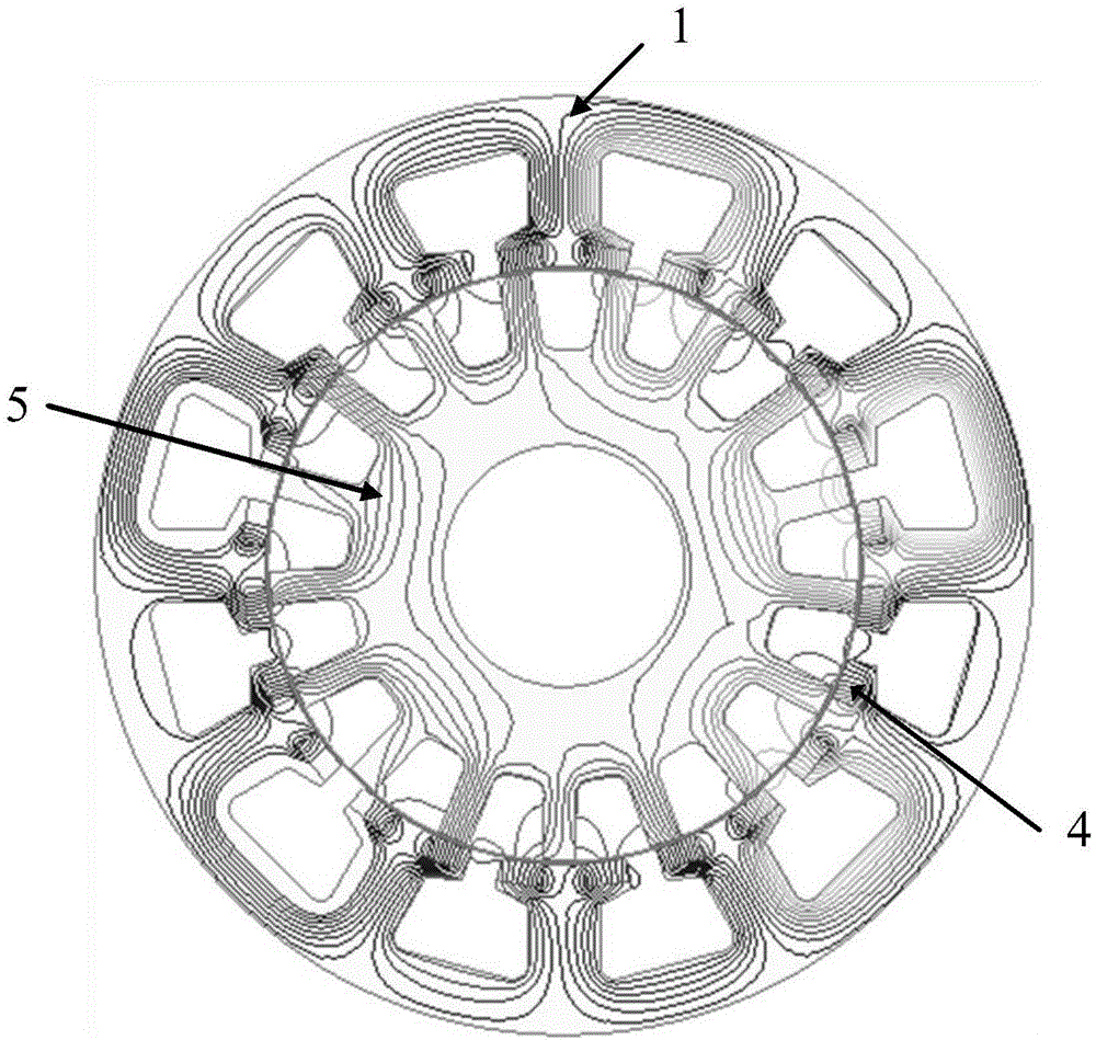
[0035] figure 1 It is a structural schematic diagram of a hybrid excitation motor according to an embodiment of the present invention. like figure 1 As shown, the hybrid excitation motor includes a stator 1 and a rotor 5, which are coaxially sleeved. In this embodiment, the stator is sleeved outside the rotor, that is, the outer stator inner rotor structure, but the present invention is not limited thereto, and it...


PUM


Abstract

The present invention discloses a hybrid excitation motor. The comprises a stator and a rotor which are coaxially sleeved with each other; grooves are formed in the inner wall of the stator which sleeves the rotor or the rotor which sleeves the stator along the circumferential direction of the inner wall; grooves are formed in the outer surface of the rotor which is sleeved with the stator or the stator which is sleeved with the rotor; a direct-current excitation winding and an alternating-current armature winding are arranged in the stator grooves; each stator tooth is provided with protrusions which protrude out from the corresponding groove and are located at side surfaces of two sides of the groove; each protrusion is provided with a permanent magnet; the polarities of the two permanent magnets arranged at the two side surfaces of each stator tooth are the same; and the polarities of the permanent magnets of two adjacent teeth are opposite. When the motor of the invention operates at a low speed, current in the direct-current winding is positive, a total excitation magnetic field can be enhanced, and the overload capacity of the motor can be improved; and when the motor operates at a high speed, the current in the direct-current winding is negative, the total magnetic field can be weakened, and the flux weakening ability of the motor can be improved. The excitation motor of the invention has the advantages of low risk of irreversible demagnetization of the permanent magnets, small magnetic resistance of excitation magnetic fields, strong flux adjustment ability of the excitation windings and reliable and stable operation. According to the motor of the invention, slip rings and electric brushes are not needed, and therefore, problems such as the problem of sparks can be avoided.

Description

technical field [0001] The invention belongs to the field of motors, and in particular relates to a hybrid excitation motor. [0002] technical background [0003] The permanent magnet synchronous motor utilizes the characteristics of high magnetic energy product of permanent magnets, so it has the advantages of high power density and high efficiency. However, since the flux linkage generated by the permanent magnet is basically not adjustable, the weak field speed regulation ability of the permanent magnet motor is weak. The excitation current of the electric excitation synchronous motor can be adjusted flexibly, so its field weakening ability is strong, but because the excitation winding and the rotor rotate synchronously, slip rings and brushes are required, sparks may be generated, and the reliability is greatly reduced; at the same time, the excitation winding will generate Copper loss, motor efficiency is not high. In order to combine the advantages of permanent magne...

Claims


Application Information

Patent Timeline
IPC IPC(8): H02K21/04H02K1/16H02K1/14H02K1/17
CPCH02K1/14H02K1/16H02K1/17H02K21/04Y02T10/64
Inventor 高玉婷曲荣海李大伟霍永胜
Owner HUAZHONG UNIV OF SCI & TECH
Learn More