
High heat radiation composite cable

A composite cable and high heat dissipation technology, which is applied in the direction of insulated cables, cables, circuits, etc., can solve the problems of poor anti-pressure protection performance, reduced work efficiency, and difficulty in pulling out cable cores, etc., to achieve increased pressure resistance and simple structure Effect

Active Publication Date: 2017-02-08
ECI HUIZHOU CABLE SCI & TECH CO LTD
View PDF5 Cites 3 Cited by
  • Summary
  • Abstract
  • Description
  • Claims
  • Application Information

AI Technical Summary

Problems solved by technology

[0002] In high-temperature operating areas, the cables are required to have strong heat dissipation to prevent the cables from working normally due to high temperatures. In addition, the cables in the prior art are often in direct contact with the PVC protective layer, so when they are cut, the cable core will be the first to be damaged. , leading to economic losses, the cables in the prior art have poor heat dissipation and poor pressure protection performance
[0003] In addition, after the exhaust gas cable is discarded, the inner cable core is often more valuable. If all of them are discarded, a lot of cost will be wasted, but the cable core is tightly wrapped by the PVC protective layer, so it is not easy to pull out the cable core , which requires cutting the PVC protective layer and then taking out the inner cable core, thus increasing the operating procedures and reducing work efficiency

Method used


Image

  • High heat radiation composite cable
  • High heat radiation composite cable

Examples


Embodiment Construction

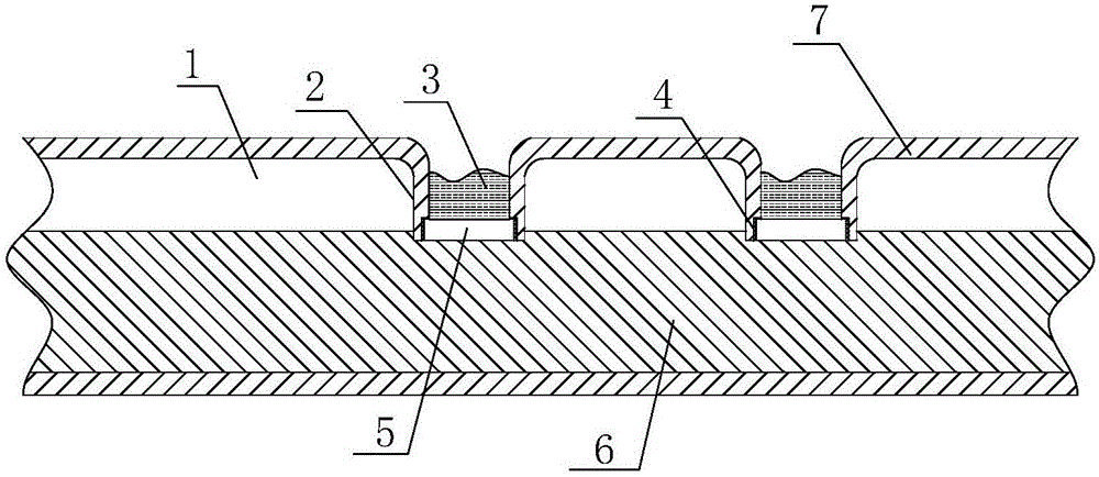
[0015] Such as figure 1 As shown, the high heat dissipation composite cable includes the outermost PVC protective layer 7 and the cable 6 installed in the PVC protective layer 7, and more than one convex portion 2 is evenly distributed on one end surface of the PVC protective layer 7, The protruding part 2 extends to one side of the cable 6 and is pressed against one end face of the cable 6. The upper end face of the protruding part 2 is open, and an accommodating cavity is formed at the opening end, and the material of the protruding part 2 and the PVC protective layer 7 is the same;

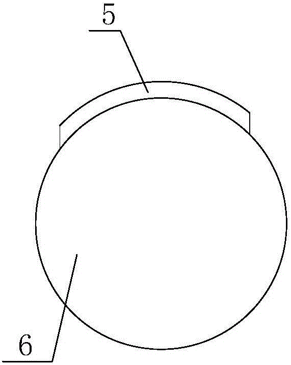
[0016] The lower end surface of the convex part 2 is provided with an arched opening, and the arched opening is sealed by an arched bottom plate 5. 6 The upper end face is in sealing contact.

[0017] In this embodiment, the lower end surface of the arched bottom plate 5 and the lower end surface of the convex part 2 are provided with an arc-shaped groove parallel to the cable, and the arc-sha...


PUM


Abstract

The invention discloses a high heat radiation composite cable. The high heat radiation composite cable comprises a PVC protection layer which is outmost and a cable installed inside the PVC protection layer; more than one projection parts are uniformly arranged on an end surface of one side of the PVC protection layer; the projection parts are extended toward one side of the cable and is tightly pressed against the end surface of one side of the cable; an opening is formed on the upper end surface of the projection part and the opening end forms a containing chamber; the materials of the projection parts and the PVC protection layer are the same; the lower end surface of the projection part is provided with an arched opening; the arched opening is sealed through an arched bottom plate; the arched bottom plate and projection part are in sealing connection through an adhesive; and the lower end surface of the arched bottom plate is in sealing contact with the upper end surface of the cable. The high heat radiation composite cable is simple in structure. Through arrangement of projection parts which are projected internally, a gap layer is formed between the PVC protection layer and the cable, which improves a pressure resistance capability and prevents a hard object from cutting the cable. Besides, the arrangement of the projection parts which are projected internally can cool down the cable, and the cable is easy to take out from the PVC protection layer in a later stage.

Description

technical field [0001] The invention relates to a cable, in particular to a high heat dissipation composite cable. Background technique [0002] In high-temperature operating areas, the cables are required to have strong heat dissipation to prevent the cables from working normally due to high temperatures. In addition, the cables in the prior art are often in direct contact with the PVC protective layer, so when they are cut, the cable core will be the first to be damaged. , leading to economic loss, the cables in the prior art have poor heat dissipation and poor pressure protection performance. [0003] In addition, after the exhaust gas cable is discarded, the inner cable core is often more valuable. If all of them are discarded, a lot of cost will be wasted, but the cable core is tightly wrapped by the PVC protective layer, so it is not easy to pull out the cable core , which requires cutting the PVC protective layer, and then taking out the inner cable core, thus increa...

Claims


Application Information

Patent Timeline
IPC IPC(8): H01B7/18H01B7/42
CPCH01B7/184H01B7/421
Inventor 何杰斌
Owner ECI HUIZHOU CABLE SCI & TECH CO LTD
Learn More