
Touch display panel

A touch display panel and touch electrode technology, which is applied in the directions of instruments, computing, and electrical digital data processing, etc., can solve the problems of thick finished products, failure to meet the bending requirements of flexible OLED products, and decreased optical transmittance. Achieve the effects of reducing the thickness of the stack, improving the bending resistance and optical transmittance, and meeting the requirements of light and thin

Active Publication Date: 2017-02-08
SHANGHAI TIANMA MICRO ELECTRONICS CO LTD +1
View PDF5 Cites 5 Cited by
  • Summary
  • Abstract
  • Description
  • Claims
  • Application Information

AI Technical Summary

Problems solved by technology

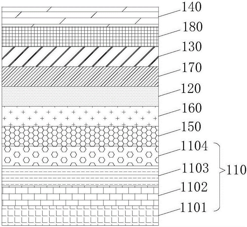
[0004] However, figure 1 The touch display panel shown has more layers, which will reduce the optical transmittance, and will also lead to a thicker finished product, which cannot meet the bendability requirements of flexible OLED products.

Method used


Image

  • Touch display panel
  • Touch display panel
  • Touch display panel

Examples


Embodiment Construction

[0043] Example embodiments will now be described more fully with reference to the accompanying drawings. Example embodiments may, however, be embodied in many forms and should not be construed as limited to the embodiments set forth herein; rather, these embodiments are provided so that this disclosure will be thorough and complete, and will fully convey the concept of example embodiments to those skilled in the art. The same reference numerals denote the same or similar structures in the drawings, and thus their repeated descriptions will be omitted.

[0044] The described features, structures, or characteristics may be combined in any suitable manner in one or more embodiments. In the following description, numerous specific details are provided in order to give a thorough understanding of embodiments of the invention. However, those skilled in the art will appreciate that the technical solutions of the present invention may be practiced without one or more of the specific...


PUM

PropertyMeasurementUnit
thicknessaaaaaaaaaa

Abstract

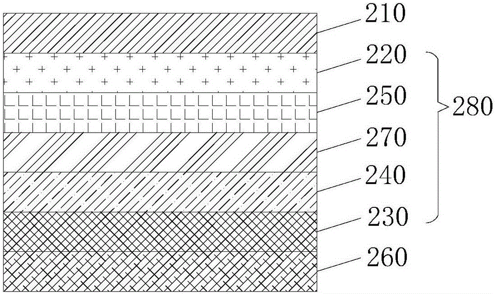
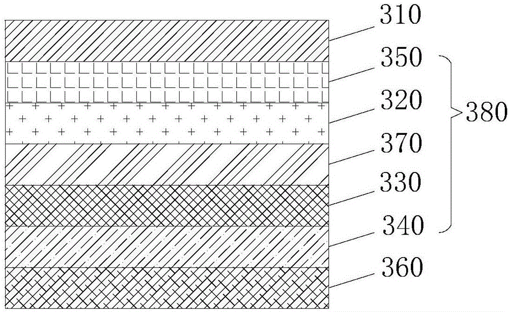
The invention discloses a touch display panel. The touch display panel comprises a display module, a linear polarizer and a composite film, wherein the linear polarizer is formed at one side of the display module; the composite film is arranged between the linear polarizer and the display module and comprises a 1 / 2 lambda wave plate, a 1 / 4 lambda wave plate, a first touch electrode layer and a second touch electrode layer; the 1 / 4 lambda wave plate is formed at the side, far from the linear polarizer, of the 1 / 2 lambda wave plate; the first touch electrode layer is formed at any side of the 1 / 4 lambda wave plate; the second touch electrode layer is formed at any side of the 1 / 2 lambda wave plate; the first touch electrode layer and the second touch electrode layer are insulated from each other. The touch display panel has the beneficial effects that touch film layers are internally arranged between the linear polarizer and the display module and are respectively bonded and fixed with the 1 / 2 lambda wave plate and the 1 / 4 lambda wave plate to form the integrated composite film, so that the lamination thickness of the panel is reduced, thus increasing the bending resistance and optical transmittance of the panel, meeting the lightening and thinning requirements of products and being applicable to flexible display panels.

Description

technical field [0001] The present invention relates to the field of touch technology, in particular to a touch display panel. Background technique [0002] As a special computer peripheral, the touch screen can provide a human-computer interaction interface between the electronic system and the user, and has been widely used in many fields, for example, in mobile phones, personal digital assistants (Personal Digital Assistant, PDA), games machine, liquid crystal display (Liquid Crystal Display, LCD), plasma display (Plasma Display Panel, PDP), etc. [0003] The structure of the existing touch display panel mostly adopts a relatively mature scheme of adding a touch film layer (ITO). Such as figure 1 As shown, the touch display panel includes a display component 110, a polarizer 120, a touch film layer 130 and a glass cover 140, wherein the display component 110, the polarizer 120, the touch film 130 and the glass cover 140 are stacked in sequence set up. figure 1 The sho...

Claims


Application Information

Patent Timeline
Patent Type & Authority Applications(China)
IPC IPC(8): G06F3/041G02F1/1333
CPCG02F1/13338G06F3/041
Inventor 周星耀王丽花曾洋刘雪宁柳晨
Owner SHANGHAI TIANMA MICRO ELECTRONICS CO LTD
Learn More