
Adaptive adjustment method for scanning mode of radar at passive working mode

A technology of adaptive adjustment and scanning mode, applied in the field of radar detection, can solve the problems of reduced observation accuracy, high dependence on radar operator's operation level, low effective data rate, etc., and achieve the optimal matching effect

Active Publication Date: 2017-02-08
THE 724TH RES INST OF CHINA SHIPBUILDING IND
View PDF4 Cites 3 Cited by
  • Summary
  • Abstract
  • Description
  • Claims
  • Application Information

AI Technical Summary

Problems solved by technology

In practice, the inventors found at least the following problems in the prior art: due to the movement of the target, in order to ensure that the target is in the best position for scanning and receiving, the radar scanning method needs to be dynamically set
The original method of manually setting the scanning mode is highly dependent on the operating level of the radar operator; it is difficult to manually set the scanning mode to ensure that the scanning center of each sector is optimally aligned with the observation target, resulting in reduced observation accuracy ; Manually setting the sector scan range is often much larger than the sector scan area required by the target to be observed. On the one hand, the effective data rate for intercepting key target radiation source information is low when the sector scan speed is fixed. There are many irrelevant targets in the scanning area, which puts great pressure on the front-end sorting data processing and computing resource maintenance

Method used


Image

  • Adaptive adjustment method for scanning mode of radar at passive working mode
  • Adaptive adjustment method for scanning mode of radar at passive working mode
  • Adaptive adjustment method for scanning mode of radar at passive working mode

Examples


Embodiment Construction

[0010] In order to make the purpose, technical solutions and advantages of the present invention clearer, the technical solutions in the present invention will be clearly and completely described below in conjunction with the accompanying drawings in the embodiments of the present invention. Obviously, the described embodiments are one of the present invention Examples, not all examples. Based on the embodiments of the present invention, all other embodiments obtained by persons of ordinary skill in the art without making creative efforts belong to the protection scope of the present invention.

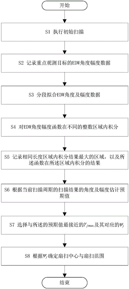
[0011] Implementation process and software flow such as figure 2 As shown, the specific description is the following process.

[0012] S1 performs initial scanning: if it is the first round of scanning, the current scanning method is determined manually; if it is not the first round of scanning, the current scanning method adopts the scanning method given in step S8 of the previous ...


PUM


Abstract

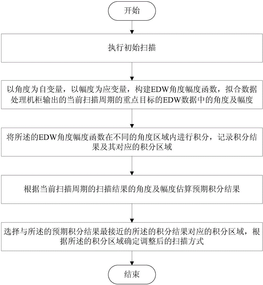
The invention discloses an adaptive adjustment method for the scanning mode of radar at a passive working mode. The adaptive adjustment method comprises the steps of building an EDW (Entity Description Word) angle-amplitude function by taking intercepted EDW angle data of a target radiation source as an independent variable and taking intercepted EDW amplitude data of the target radiation source as a dependent variable, and fitting an angle and an amplitude in target EDW data, which is outputted by a data processor, in the current scanning period; integrating the built EDW angle-amplitude function in different angle areas, and recording an integrating result and a corresponding integrating area; estimating an expected value according to the EDW angle and amplitude acquired in the current scanning period; and selecting an integrating area value corresponding to an EDW angle-amplitude function integrating result which is the closest to the expected value, and determining a sector-scan center and a sector-scan range according to the integrating area value. Through accumulation for intensity values of radiation intercepted by a key radiation source target in different angle ranges, the adaptive adjustment method can realize recognition for an area in which the target appears, thereby adaptively adjusting the sector-scan center and the sector-scan range of the radar.

Description

technical field [0001] The invention relates to the field of radar detection, in particular to a method for adaptively adjusting the scanning mode of the radar in a passive working mode. Background technique [0002] The main scanning method of fan beam radar is sector scanning. When a certain area needs to be observed carefully, the beam can move back and forth within the required range, that is, sector scanning (referred to as sector scanning). The two sides of the fan form the scan boundaries, and a clockwise or counterclockwise scan from one boundary to the other constitutes a scan cycle. [0003] In the passive working mode, the radar itself does not emit electromagnetic waves, and extracts information such as the target's spatial position, motion state, and property characteristics through the intercepted target radiation source radiation signal. The radiation signal of the target radiation source after sorting and processing by the data processing cabinet is usually ...

Claims


Application Information

Patent Timeline
IPC IPC(8): G01S3/58G01S11/04G01S11/06
CPCG01S3/58G01S11/04G01S11/06
Inventor 陆翔田田王善民裴江涂刚毅
Owner THE 724TH RES INST OF CHINA SHIPBUILDING IND
Learn More