
Circulation heating device and flowing path control method for heat collecting liquid

A heating device and heat collection technology, applied in the field of solar radiation heat energy utilization, can solve problems such as large fluctuation of heat collection temperature and heat collection, large influence of heat collection temperature by solar radiation, and inability to dynamically adjust the heat collection level of the heat collector. , to achieve the effect of improving stability and efficiency, improving adaptability, and improving heat collection efficiency

Active Publication Date: 2017-02-08
BEIJING UNIVERSITY OF CIVIL ENGINEERING AND ARCHITECTURE
View PDF5 Cites 4 Cited by
  • Summary
  • Abstract
  • Description
  • Claims
  • Application Information

AI Technical Summary

Problems solved by technology

However, at present, the heat-collecting liquid in solar collectors relies on natural convection or pump flow. The heat-collecting temperature is greatly affected by solar radiation, and the heat-collecting temperature and heat-collecting amount fluctuate greatly. It is impossible to adjust the heat-collecting level of the collector according to the actual demand for heating. Make dynamic adjustments

Method used


Image

  • Circulation heating device and flowing path control method for heat collecting liquid
  • Circulation heating device and flowing path control method for heat collecting liquid
  • Circulation heating device and flowing path control method for heat collecting liquid

Examples


Embodiment 1

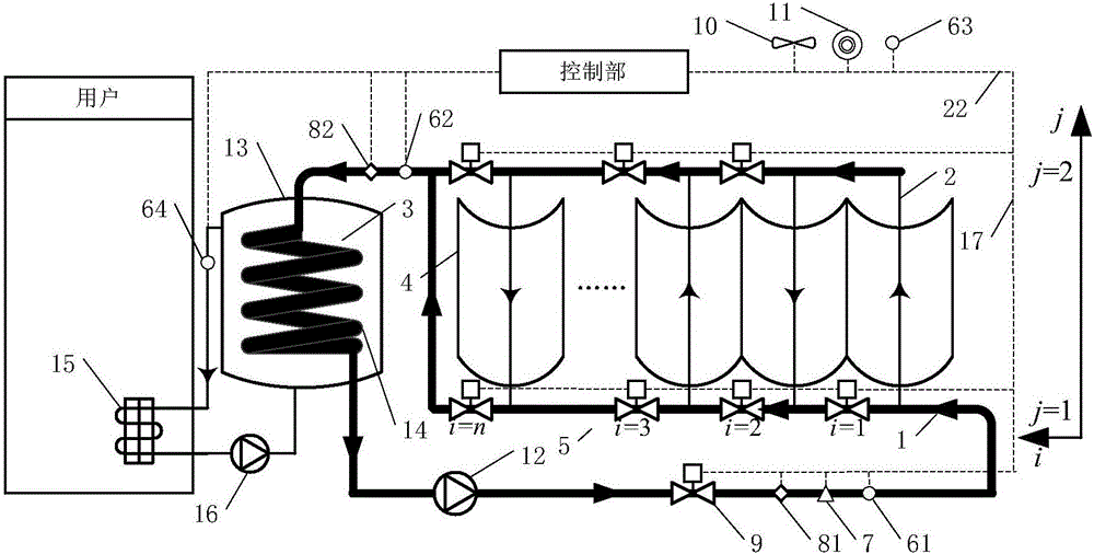
[0028] figure 1 A schematic structural diagram of a circulating heating device according to an embodiment of the present invention is shown, in which the heat collection level of the heat collector meets the heating requirements mainly by adjusting the path of the instant hot liquid.

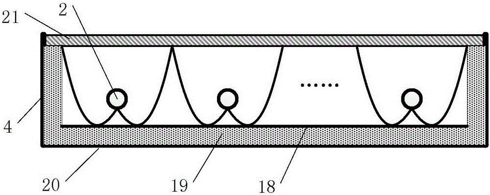
[0029] Such as figure 1As shown, in the case that the heat-collecting liquid is a medium other than the medium that can directly provide heating for the user, the circulation heating device mainly includes: a heat storage tank 13 with a heat exchanger 14 inside, and a heat storage tank 13 for heat exchange The collector provides the set heating temperature to the collector. The heat collector mainly includes a casing and a heat collecting part placed in the casing; the casing is mainly used as a carrier of the heat collecting part, and ensures that sunlight can pass through the cover glass 21 of the casing to irradiate the heat collecting part. further as figure 2 As shown, the structure o...


PUM

PropertyMeasurementUnit
Diameteraaaaaaaaaa

Abstract

The invention relates to a circulation heating device and a flowing path control method for heat collecting liquid. The device comprises a heating loop and a solar heat collector, wherein the heating loop comprises a heat storing water tank, a heating tail end and a circulating water pump; the solar heat collector comprises a shell and a heat collecting part arranged in the shell; the heat collecting part comprises an inlet liquid dividing pipe, an outlet liquid collecting pipe and a plurality of heat collecting units arranged between the inlet liquid dividing pipe and the outlet liquid collecting pipe in parallel; each heat collecting unit comprises a compound parabolic concentrator and a capillary pipe heat absorber arranged on the compound parabolic concentrator in a spanning manner; and the heat collecting liquid forms a flowing path among the inlet liquid dividing pipe, the outlet liquid collecting pipe and at least part of the capillary pipe heat absorbers, and a heat exchanger in a heat accumulator enables the flowing path to form a closed loop. The number of the capillary pipe heat absorbers connected to the flowing path is adjustable. The heating device can meet heating requirements by adjusting the flowing path of the heat collecting liquid.

Description

technical field [0001] The invention relates to the field of utilization of solar radiant heat energy, in particular to a circulation heating device and a process control method for heat collecting liquid. Background technique [0002] At present, the heat collecting liquid in the solar heat collector flows by natural convection or pump. The heat collector temperature and flow are passively adjusted, and it is impossible to dynamically adjust the operating state (heat collector temperature and flow) according to actual needs to adapt to changes in weather and usage requirements; and solar collectors usually use flat-plate heat-absorbing surfaces to absorb solar energy. Moreover, the temperature of the heat-absorbing surface is generally higher than that of the heat-absorbing tube, forming a high-temperature radiation surface and a heat leakage surface, which affect the heat collection efficiency. [0003] At present, the improvement of solar heat collectors is mainly carrie...

Claims


Application Information

Patent Timeline
IPC IPC(8): F24D3/00F24D3/02F24D19/10F24J2/32F24J2/46F24J2/12F24J2/40F24S10/95F24S23/71
CPCF24D3/005F24D3/02F24D19/1006Y02E10/44
Inventor 徐荣吉胡文举吴青平王瑞祥王华生胡洁
Owner BEIJING UNIVERSITY OF CIVIL ENGINEERING AND ARCHITECTURE
Learn More