Three-dimensional vibration isolation support with adjustable vertical early-stage rigidity

A shock-isolation support and vertical shock-isolation technology, applied in the direction of shock-proof, building components, building types, etc., can solve the problems of reducing the cost of shock-isolation, shortening the effective working length of the spring, not being able to stretch, energy-consuming and shock-absorbing, etc., to achieve The effect of buffering tensile and compressive shocks, reducing the cost of wind and shock resistance, and reducing the risk of overturning

Pending Publication Date: 2017-02-08
ANHUI XINZE TECH CO LTD
View PDF9 Cites 2 Cited by
  • Summary
  • Abstract
  • Description
  • Claims
  • Application Information

AI Technical Summary

Problems solved by technology

Although the scheme described in this patent application can improve the tensile strength of the three-dimensional seismic isolation device to resist the huge tension generated by the swaying or even overturning of high-rise buildings in an earthquake, the following deficiencies still exist: 1. The spring isolation The support can only be compressed for energy consumption and shock absorption, but cannot be stretched for energy consumption and shock absorption; 2. The spring isolation support cannot preset the early stiffness, which is not convenient for presetting the seismic intensity to reduce the cost of isolation
However, this invention still has the following disadvantages: 1. The load connecting rod is balanced under the joint action of two groups of disc springs. Although the preload of the two groups of disc springs can be adjusted, no matter how they are adjusted, the The force of the disc spring on the load connecting rod is a set of equal and opposite forces. Just applying any external force on the load connecting rod will destroy this balance and deform the two sets of disc springs. Therefore, the 2. In this invention, two sets of disk springs must be used together to provide damping when the damper is under compression or tension load, which not only causes a certain waste, but also makes the damper greatly increased in length
It can be seen that although the stiffness of the spring in the patent application scheme can be changed, the effective working length of the spring is not only significantly shortened, but also can only be compressed for energy consumption and vibration reduction, and cannot be stretched for energy consumption and vibration reduction.

Method used


Image

  • Three-dimensional vibration isolation support with adjustable vertical early-stage rigidity
  • Three-dimensional vibration isolation support with adjustable vertical early-stage rigidity
  • Three-dimensional vibration isolation support with adjustable vertical early-stage rigidity

Examples


example 1

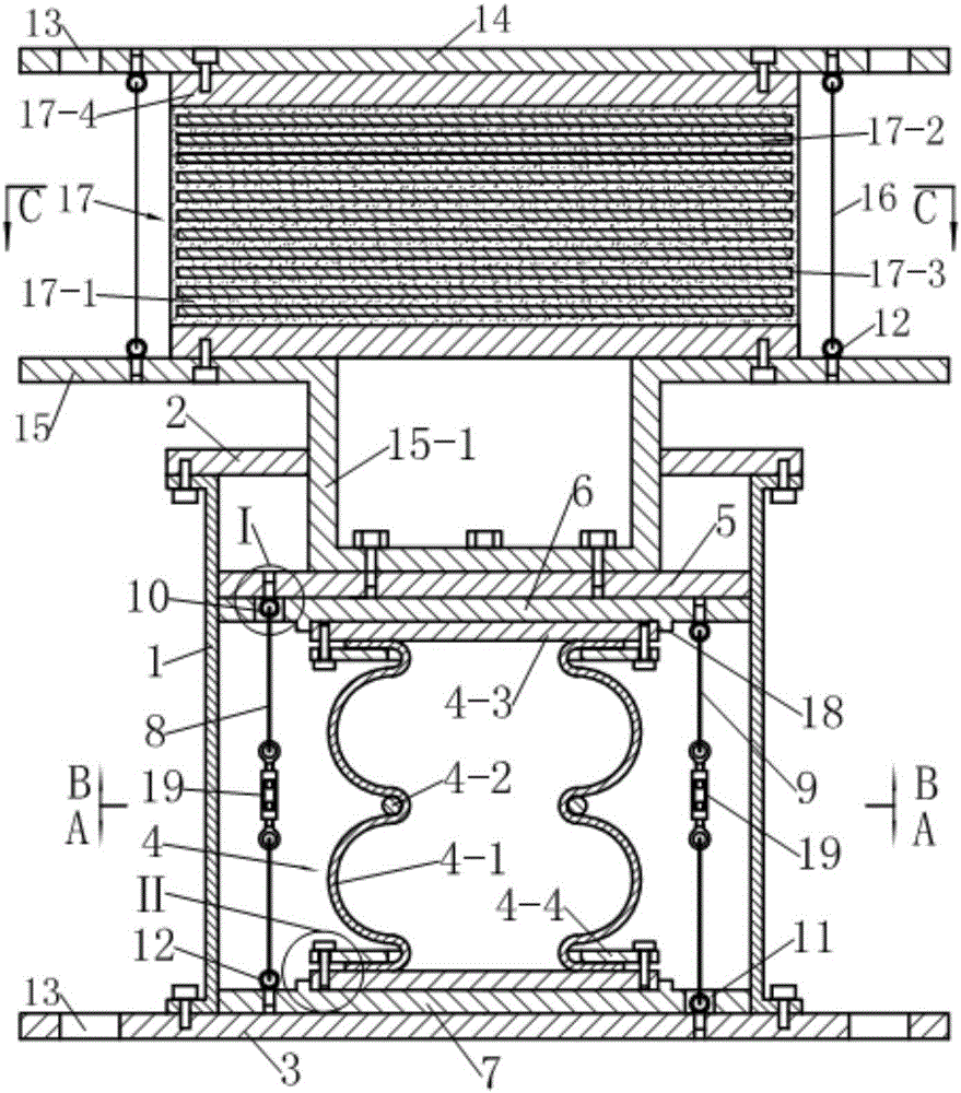
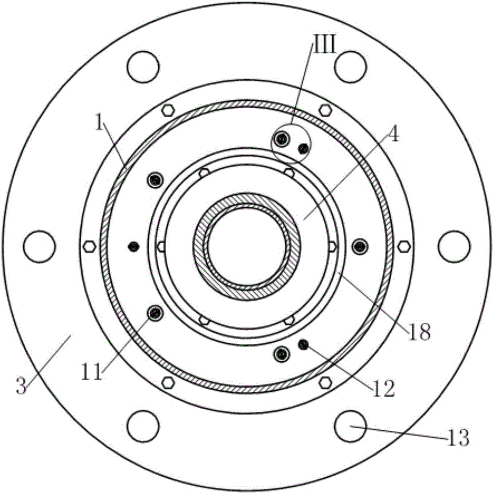
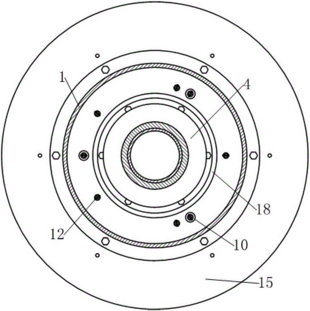
[0036] see figure 1 , the three-dimensional seismic isolation bearing in this example is composed of laminated rubber isolation bearings and vertical isolation bearings connected in series up and down.

[0037] see figure 1 with Figure 4 , the laminated rubber shock-isolation bearing includes an upper connecting plate 14, a lower connecting plate 15, a laminated rubber pad 17 clamped between the upper and lower connecting plates and six tensile steel cables 16; wherein, the upper Both the connecting plate 14 and the lower connecting plate 15 are disc-shaped, and the edge of the upper connecting plate 14 is provided with mounting holes 13; the main body of the laminated rubber pad 17 is alternately composed of a layer of rubber 17-1 and a layer of steel plate 17-2 After lamination, it is molded and vulcanized, and a rubber protective layer 17-3 is naturally formed around it during the process of molded vulcanization. The upper and lower end surfaces of the main body of th...

example 2

[0051] This example has the following differences from Example 1:

[0052] see Figure 8-10 , the first group of preloaded steel cables 8 and the second group of preloaded steel cables 9 are composed of three preloaded steel cables. The number of said rigging turnbuckles 19 is reduced to six, and they are connected in series in the middle of each preloaded steel cable respectively.

[0053] The above-mentioned implementation method of this example is the same as Example 1.

example 3

[0055] see Figures 11 to 13 , The difference between this example and Example 2 is that the first group of preloaded steel cables 8 and the second group of preloaded steel cables 9 are composed of five preloaded steel cables. The number of said rigging turnbuckles 19 is reduced to ten, and they are respectively connected in series at the middle part of each preloaded steel cable.

[0056] Other implementations of this example other than the above are the same as Example 2.


PUM


Abstract

The invention discloses a three-dimensional vibration isolation support with adjustable vertical early-stage rigidity. The three-dimensional vibration isolation support comprises a stacked rubber vibration isolation support and a vertical vibration isolation support which are sequentially connected in series from top to bottom, and is characterized in that a reverse pressing device is further arranged in a guide sleeve of the vertical vibration isolation support; the reverse pressing device comprises two groups of pre-pressing steel ropes and two floating pressing plates, wherein the two groups of pre-pressing steel ropes are distributed between a rubber air spring and the guide sleeve respectively; one ends of one group of the pre-pressing steel ropes are fixed on the floating pressing plate adjacent to a driving pressing plate, and the other ends of one group of the pre-pressing steel ropes penetrate through the floating pressing plate adjacent to a base to be fixed on the base; one ends of the other group of pre-pressing steel ropes are fixed on the floating pressing plate adjacent to the base respectively, and the other ends of the other group of pre-pressing steel ropes penetrate through the floating pressing plate adjacent to the driving pressing plate to be fixed on the driving pressing plate; a rigging spiral buckle is connected on each pre-pressing steel rope in series; and when the two groups of pre-pressing steel ropes are tensioned, the rubber air spring is clamped between the two floating pressing plates all the time.

Description

technical field [0001] The invention relates to a building anti-vibration (or shock) device, in particular to a three-dimensional shock-isolation device in which a sandwich steel plate rubber pad is connected in series with a vertical shock-isolation support. Background technique [0002] The seismic isolation device is an anti-seismic isolation device installed between the building and the foundation. The early seismic isolation devices were mainly two-dimensional isolation bearings (laminated rubber isolation bearings) composed of rubber and thin steel plates alternately laminated, which could only isolate the horizontal component of seismic waves. With the improvement of people's understanding of the multi-dimensional characteristics of earthquakes, three-dimensional seismic isolation devices have gradually attracted the attention of researchers in this field. The most common three-dimensional isolation device is composed of laminated rubber isolation bearings connected ...

Claims


Application Information

Patent Timeline
Patent Type & Authority Applications(China)
IPC IPC(8): E04B1/36E04B1/98E04H9/02
CPCE04B1/36E04H9/021E04H9/022E04H9/0235
Inventor 沈珊胡济福胡济全
Owner ANHUI XINZE TECH CO LTD
Why Eureka
Try Eureka