
Automatic transmission rack

A technology for conveying materials and racks, which is applied in the field of automatic conveying racks, which can solve the problems that cannot meet the needs of industrial production, time-consuming and labor-intensive effects, and the transmission shaft cannot bear load, etc., and achieve the effects of small resistance, flexible rotation, and improved production efficiency

Inactive Publication Date: 2017-02-08
无锡昊康通用机械有限公司
View PDF9 Cites 7 Cited by
  • Summary
  • Abstract
  • Description
  • Claims
  • Application Information

AI Technical Summary

Problems solved by technology

At present, most of the industry is manually driven, which is time-consuming and laborious and often has poor results. Influenced by experience, inaccurate positioning and imprints formed by secondary touches on the processed surface are unacceptable to customers
[0003] In the existing technology, in addition to the original manual operation, there is also the use of PVC conveyor belt transmission, or only the transmission without photoelectric induction, or the positioning device has no distance adjustment function, or the design of the transmission shaft is simple and cannot bear the load and run efficiently for a long time , the function is not comprehensive enough to meet the needs of industrial production

Method used


Image

  • Automatic transmission rack
  • Automatic transmission rack
  • Automatic transmission rack

Examples


Embodiment Construction

[0024] The present invention will be described in further detail below in conjunction with accompanying drawing description and specific embodiment:

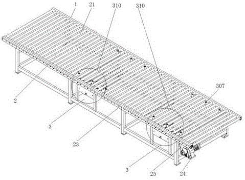
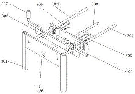
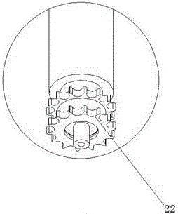
[0025] Such as figure 1 As shown, an automatic conveying rack includes a frame 1, and a conveying device 2 is arranged on the frame 1, and the conveying device 2 includes a plurality of transmission shafts 21, double transmission gears 22, a protective cover 23, a motor 24 and an electrical control box 25, the plurality of transmission shafts 21 are equidistantly arranged above the frame 1, one transmission shaft 21 corresponds to a double transmission gear 22, and the double transmission gear 22 is installed on one end of the transmission shaft 21, the Both ends of the drive shaft 21 are provided with a protective cover 23, and the motor 24 and the electrical control box 25 are installed at the end of the frame 1; the frame 1 also includes a pushing positioning device 3, and the pushing positioning device 3 is located in the tr...


PUM


Abstract

The invention relates to a transmission rack and particularly relates to the transmission feeding and discharging of automation equipment. The transmission rack comprises a rack, wherein a conveying device is arranged on the rack. The transmission rack is characterized in that the conveying device comprises a plurality of transmission shafts, double-drive gears, a protective cover, a motor and an electric control cabinet, the plurality of transmission shafts are arranged above the rack at equal intervals, one transmission shaft corresponds to one double-drive gear, and a pushing locating device comprises a support frame, a baffle, a first fixing rod, a second fixing rod, a first pushing cylinder, a second pushing cylinder, a locating guide wheel, pushing rails, a regulating screw and a photoelectric sensor. The transmission rack can carry out butt joint on the automation equipment, can be widely applied to automatic laminating machines, automatic pushing plate packers and automatic conveying machines, is accurate in locating, increases the working efficiency due to full automatic operation, is simple in structure and is convenient to popularize and apply.

Description

technical field [0001] The invention relates to a mechanical conveying device, in particular to an automatic conveying material rack. Background technique [0002] At present, in the process of processing various materials, material transmission will be encountered, especially for materials such as plates, stones, and woods. During the process of polishing, wire drawing, and mirroring, it is often necessary to accurately locate and enter the equipment for processing, and to pack neatly when outputting And when processing film, transmission, counting and precise positioning are required. At present, most of the industry is manually driven, which is time-consuming and laborious and often has poor results. Influenced by experience, inaccurate positioning and imprints formed by secondary touches on the processed surface are unacceptable to customers. [0003] In the existing technology, in addition to the original manual operation, there is also the use of PVC conveyor belt tra...

Claims


Application Information

Patent Timeline
Patent Type & Authority Applications(China)
IPC IPC(8): B65G13/02B65G43/08B65G47/24
CPCB65G13/02B65G43/08B65G47/24
Inventor 陈中胜陈虎
Owner 无锡昊康通用机械有限公司
Learn More