
An operational mechanical device and its electrical system

A technology of electrical systems and mechanical equipment, applied in the fields of electric energy management, electric vehicles, transportation and packaging, etc., can solve the problems that the electrical system of the main vehicle occupies a large space, the overall space of the main vehicle is tight, and the counterweight is unreasonable, etc., to achieve Lightweight, reduced space and important requirements, the effect of easy maintenance

Active Publication Date: 2019-07-26
ZHUZHOU CSR TIMES ELECTRIC CO LTD
View PDF5 Cites 0 Cited by
  • Summary
  • Abstract
  • Description
  • Claims
  • Application Information

AI Technical Summary

Problems solved by technology

[0003] An operational mechanical equipment is a typical mechanical equipment that requires the above electrical system, such as a vehicle that can run at high speed. The electrical system of the mechanical equipment includes transformers, converters and power equipment. When configuring the electrical system, the The converter and the power equipment in the electrical system are arranged on the main vehicle together. In order to save space, reduce the weight of the vehicle, and reduce the size of the main vehicle, an auxiliary vehicle is usually equipped outside the main vehicle for The transformer in the above electrical system is installed, and the voltage provided by the power supply equipment is stepped down and then output to the converter of the main vehicle. The auxiliary vehicle is not equipped with power equipment and moves together under the power drive of the main vehicle. However, the inventor found in the process of realizing the present invention that since the circuit structure of the converter is relatively complex and the power is relatively large during operation, a relatively large-power cooling device is required to cool it down. Another convenience is to consider the convenience of maintenance. The electrical system of the main vehicle occupies a large space and is heavy, which makes the overall space of the main vehicle tight and the counterweight is unreasonable, which is contradictory to the development direction of lightweight and miniaturized vehicles

Method used


Image

  • An operational mechanical device and its electrical system
  • An operational mechanical device and its electrical system
  • An operational mechanical device and its electrical system

Examples


Embodiment 1

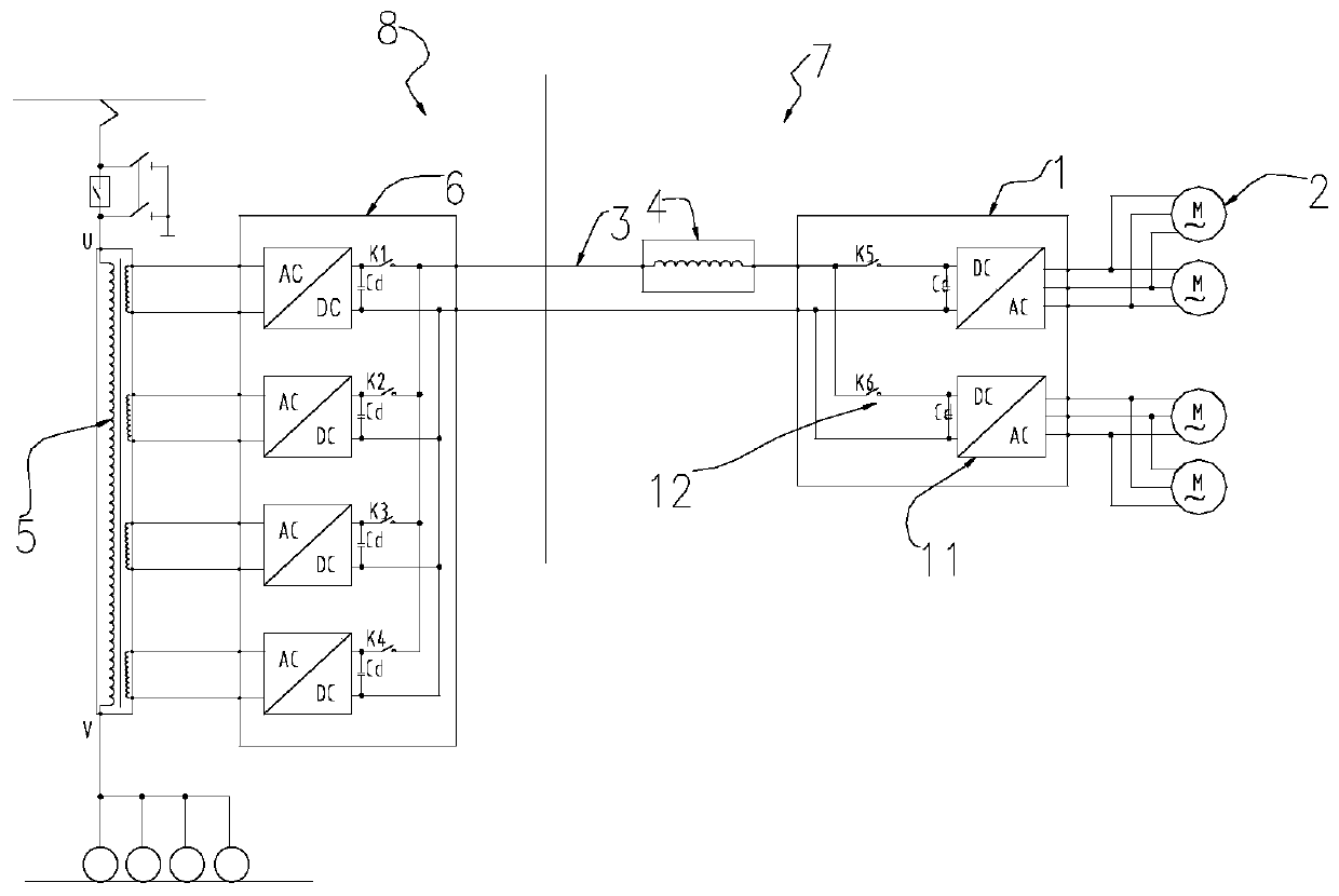
[0025] Please refer to figure 2 , this embodiment provides an electrical system of an operable mechanical device, including a traction inverter 1 and a traction motor 2 . Wherein, the traction inverter 1 obtains DC power from the power supply equipment through the DC bus 3 , and converts the DC power into three-phase AC power to supply to the traction motor 2 .

[0026] Optionally, refer to Figure 7 , four traction motors 2 are connected in parallel at the output end of the traction inverter 1 in this embodiment.

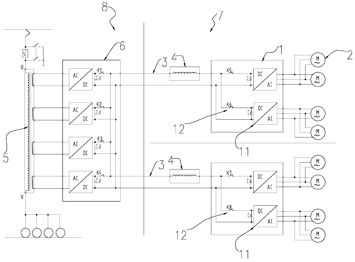
[0027] Optionally, refer to figure 2 , image 3 and Figure 4 , the traction inverter 1 in this embodiment includes two inverter units, and each inverter unit is connected to two parallel traction motors 2 respectively. The number of traction inverter 1 can be one, such as figure 2 , can also be two or more, such as image 3 .

[0028] Optionally, refer to Figure 8 , the traction inverter 1 in this embodiment includes four traction inverter units 11 , ...

Embodiment 2

[0034] Please refer to Figure 2 to Figure 9 In this embodiment, on the basis of Embodiment 1, an inductance device is added on the DC bus 3, and the inductance device is arranged at the current input end of the traction inverter 1, which is used for the current fluctuation on the DC bus 3 to avoid short circuit conditions The fault current under the fault is too large, resulting in damage to electrical equipment. The inductive device is preferably a line reactor 4 .

Embodiment 3

[0036] Please refer to Figure 2 to Figure 9 In this embodiment, on the basis of Embodiment 1 and Embodiment 2, a DC conversion device is added, and the DC conversion device is connected to the power supply device, and is used to convert the unidirectional AC power on the power supply device into DC power, and then transmit it through the DC bus 3 to the traction inverter 1, and then to the traction motor 2. The DC conversion equipment in this embodiment specifically includes a traction transformer 5 and a traction rectifier 6, wherein the traction transformer 5 is connected to the power supply equipment for stepping down the unidirectional AC power provided by the power supply equipment, and the traction rectifier 6 is connected to the traction transformer 5 , which is used to convert the stepped-down unidirectional alternating current into direct current. The DC conversion device in this solution can also be a power electronic transformer 9 .

[0037]The purpose of adding ...


PUM


Abstract

The invention discloses an electric system. The electric system comprises a traction inverter and a traction motor, wherein the traction inverter is used for acquiring direct current from a power supply device through a direct-current bus, and the direct current is converted into three-phase alternating current which is supplied to the traction motor. On the basis, the invention also provides mechanical equipment capable of operating. The mechanical equipment comprises a vehicle containing a power device, and also can be combination of the vehicle containing the power device and a vehicle which does not contain the power device. Compared with electric equipment containing a converter and a power device in the prior art, the electric system has the advantages that the power of the inverter is smaller than that of the converter, the weight is low, needed multiple cooling modes are achieved, the maintenance is convenient, the requirement that the occupying space and the weight of the electric system are reduced is realized, meanwhile, the maintenance convenience and cooling requirement of the electric system can be considered, and light weight and miniaturization of the mechanical equipment capable of operating can be realized, so that the integral balance weight and space distribution can be facilitated.

Description

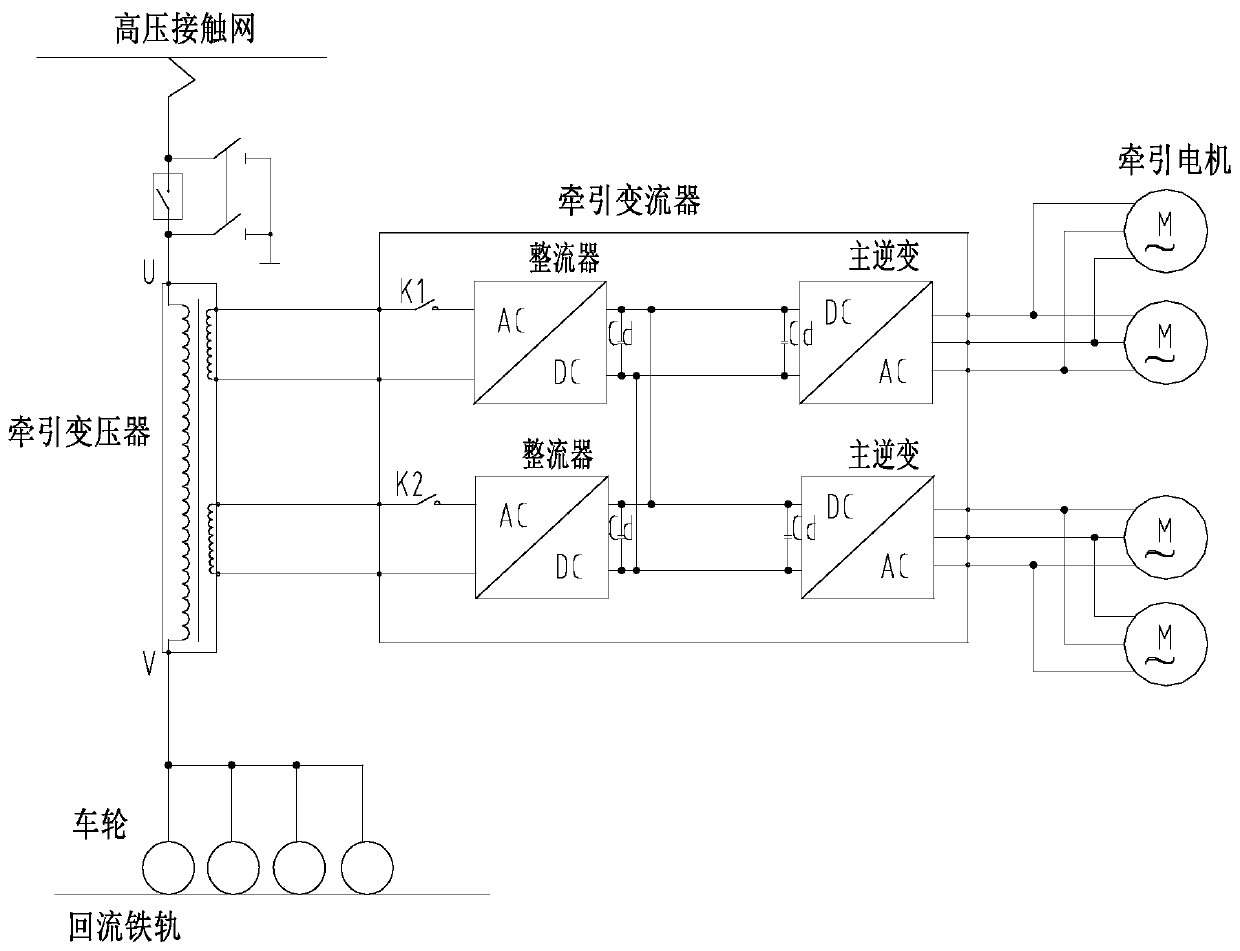
technical field [0001] The present application relates to the field of electromechanical technology, and in particular, to an operational mechanical device and its electrical system. Background technique [0002] For electrical systems of existing mechanical equipment, please refer to figure 1 , when the power equipment of mechanical equipment needs a three-phase AC power supply with adjustable frequency and voltage, the power supply is generally realized through a converter, that is, the single AC power provided by the power supply equipment is first converted into DC power through the converter, and then the DC power is converted into DC power. converted into the three-phase alternating current and output to the power equipment. When the voltage of the power supply equipment is too high for the mechanical equipment, it is necessary to add a transformer to step down the AC power of the power supply equipment. [0003] An operational mechanical equipment is a typical mecha...

Claims


Application Information

Patent Timeline
Patent Type & Authority Patents(China)
IPC IPC(8): B60L50/60
CPCB60L50/51Y02T10/70Y02T10/72
Inventor 冯江华尚敬刘海涛章志兵高峻刘大
Owner ZHUZHOU CSR TIMES ELECTRIC CO LTD
Learn More