Novel anticollision injection mold

An injection mold and anti-collision technology, which is applied in the field of new anti-collision injection molds, can solve problems such as time-consuming and laborious, difficult to reset the ejector pin, and lack of counting function

Inactive Publication Date: 2017-02-08
TIANJIN LIANXINYING PLASTIC TECH
View PDF0 Cites 1 Cited by
  • Summary
  • Abstract
  • Description
  • Claims
  • Application Information

AI Technical Summary

Problems solved by technology

[0002] In modern society, the use of plastic products is becoming more and more extensive. Injection mold is a kind of tool ; It is also to give plastic products a complete structure and accurate size tool ,The injection mold consists of two parts, the movable mold and the fixed mold. The movable mold is installed on the movable template of the injection molding machine, and the fixed mold is installed on the fixed template of the injection molding machine. During injection molding, the movable mold and the fixed mold are closed to form a pouring system. And the cavity, when the mold is opened, the movable mold and the fixed mold are separated, and the plastic product

Method used


Image

  • Novel anticollision injection mold

Examples


Embodiment 1

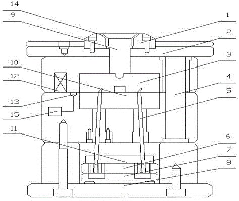
[0009] A new type of anti-collision injection mold, including: positioning ring 1, upper fixing plate 2, die 3, guide post 4, ejector rod 5, upper ejector plate 6, lower ejector plate 7, lower fixing plate 8, sprue 9. Punch 10, limit controller 11, limit block 12, photoelectric switch 13, detachable sprue sleeve 14, counter 15, positioning ring 1 is installed on the upper fixing plate 2, and detachable gate is installed on the positioning ring 1 Set 14, the sprue 9 is opened under the detachable sprue sleeve 14, the die 3 is installed under the upper fixed plate 2, the guide post 4 is installed on one side of the die 3, the limit block 12 is installed on the side of the die 3, and the limit block 12 The photoelectric switch 13 is installed below, the counter 15 is connected under the photoelectric switch 13, the punch 10 is installed under the die 3, the ejector rod 5 is installed under the punch 10, the upper ejector plate 6 is installed under the punch 10, and the upper eject...

Embodiment 2

[0011] The injection molding machine injects the raw material into the runner 9 through the detachable sprue sleeve 14, the raw material flows into the space between the concave mold 3 and the convex mold 10 to cool and form, the upper and lower molds are opened, and the ejector rod 5 ejects the workpiece, and the photoelectric The switch 13 loses the barrier and triggers the counter 15, and the counter 15 adds one to the value. If the ejector rod 5 is pushed out of the workpiece, if it is not reset, the limit controller 11 will control the limit block 12 to stand between the upper and lower molds, so that the mold cannot be moved again. Clamp the mold to prevent the mold from being damaged when the ejector pin 5 is not reset and closes the mold again. If the sprue sleeve has residual raw materials, the staff can separately disassemble the detachable sprue sleeve 14 for cleaning without removing the positioning ring 1 entirely.


PUM


Abstract

The invention provides a novel anticollision injection mold including a positioning ring, an upper fixed plate and the like and characterized in that the novel anticollision injection mold also includes a limit controller, a limit block, a photoelectric switch, a detachable sprue bush and a counter; the upper fixed plate is provided with the positioning ring; the positioning ring is provided with the detachable sprue bush; a pouring gate is arranged below the detachable sprue bush; a female mold is arranged below the upper fixed plate, one side of the female mold is provided with a guide pillar, and the other side of the female mold is provided with the limit block. The limit controller, the limit block, the photoelectric switch, the detachable sprue bush and the counter are added; if an ejection rod is not reset, a case that the ejection rod is not reset and the mold is assembled again to eject the mold to be bad is avoided; the photoelectric switch is triggered when the mold is opened, the counter is allowed to count, the effectiveness of piece automatic counting is achieved, artificial recording is not needed, and the manpower is saved; after injection molding, the sprue bush can be dismounted alone and is cleaned, the whole positioning ring is not required to be dismounted, and a plenty of time is saved.

Description

technical field [0001] The invention relates to an injection mold, in particular to a novel anti-collision injection mold. Background technique [0002] In modern society, the use of plastic products is becoming more and more extensive. Injection mold is a kind of tool ; It is also to give plastic products a complete structure and accurate size tool ,The injection mold consists of two parts, the movable mold and the fixed mold. The movable mold is installed on the movable template of the injection molding machine, and the fixed mold is installed on the fixed template of the injection molding machine. During injection molding, the movable mold and the fixed mold are closed to form a pouring system. And the cavity, when the mold is opened, the movable mold and the fixed mold are separated, and the plastic product is ejected through the ejector pin, but it is often difficult to reset after the ejector pin is ejected, and the mold will be damaged when the mold is closed again...

Claims


Application Information

Patent Timeline
IPC IPC(8): B29C45/26B29C45/84
CPCB29C45/2602B29C45/2673B29C45/844B29C2045/1788
Inventor 任富疆王伟
Owner TIANJIN LIANXINYING PLASTIC TECH
Why Eureka
Try Eureka