
A method and system for auto diagnostic flashing electronic control unit

A technology for electronic control unit and automobile diagnosis, applied in electrical components, transmission system, digital transmission system, etc., can solve problems such as slowing down production speed, achieve the effect of reducing the number of stations, improving stability, and simplifying algorithms

Active Publication Date: 2020-10-16
GUANGZHOU AUTOMOBILE GROUP CO LTD
View PDF15 Cites 0 Cited by
  • Summary
  • Abstract
  • Description
  • Claims
  • Application Information

AI Technical Summary

Problems solved by technology

Based on this status quo, if the diagnostic equipment does not support flashing multiple CAN lines at the same time, the production speed will be greatly slowed down

Method used


Image

  • A method and system for auto diagnostic flashing electronic control unit
  • A method and system for auto diagnostic flashing electronic control unit
  • A method and system for auto diagnostic flashing electronic control unit

Examples


Embodiment 1

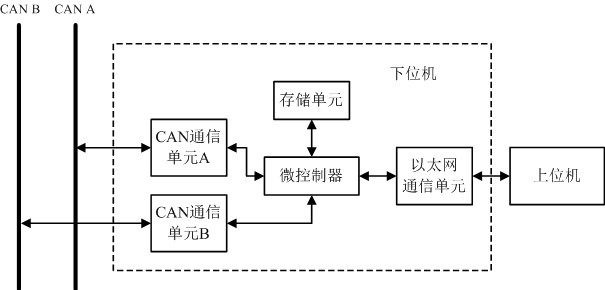
[0083] please refer again image 3 As shown, based on the first embodiment of the present invention, the second embodiment of the present invention provides a system for flashing an electronic control unit for automobile diagnosis, including:

[0084] An upper computer and a lower computer, wherein the upper computer communicates with the lower computer through the User Datagram Protocol UDP;

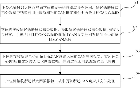
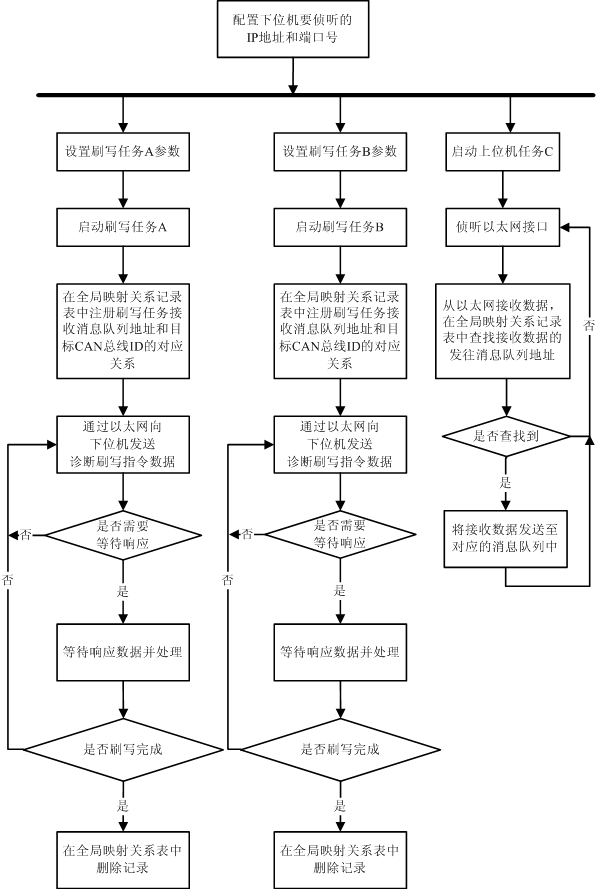
[0085] The upper computer sends diagnostic flashing instruction data to the lower computer through the Ethernet bus, and the diagnostic flashing instruction data carries a CAN message for diagnostic flashing and at least two target CAN bus IDs;

[0086] The lower computer receives the diagnostic flashing command data, extracts the CAN message in the diagnostic flashing command data, and sends the CAN message to at least two target CAN buses according to the target CAN bus ID ;

[0087] The lower computer receives the CAN response message returned by the at least two target CAN buses, en...


PUM


Abstract

The invention provides a method and a system for diagnosing and flashing the electronic control unit of a vehicle. The method comprises the following steps: an upper computer sends diagnosing and flashing instruction data to a lower computer via an Ethernet bus, wherein the diagnosing and flashing instruction data carries a CAN message for diagnosing and flashing and at least two target CAN bus IDs; the lower computer receives the diagnosing and flashing instruction data, extracts a CAN message in the data, and sends the CAN message to at least two target CAN buses according to the target CAN bus IDs; the lower computer receives a returned CAN response message, packages the CAN response message into an Ethernet data frame, and sends the Ethernet data frame to the upper computer via the Ethernet bus; the upper computer receives the Ethernet data frame, extracts the CAN response message from the Ethernet data frame, and processes the CAN response message; and the upper computer and the lower computer communicate via a user datagram protocol UDP. The electronic control units on multiple CAN buses can be flushed at the same time, and thus, the production efficiency is improved.

Description

technical field [0001] The invention relates to the technical field of automobiles, in particular to a method and system for rewriting an electronic control unit for automobile diagnosis. Background technique [0002] When a car is produced off-line, the rate at which diagnostics are flashed to the electronic control unit (ECU) on the vehicle seriously affects the pace of production. At present, the communication technology between Ethernet and CAN bus network is relatively mature. In terms of automotive diagnostic flashing, CANoe from Vector Company, Vehicle Spy from IntrepidCS Company and various after-sales diagnostic instruments are widely used. These diagnostic devices support both wired Ethernet and wireless Ethernet to diagnose and write the ECU on the CAN line, but basically they do not support the function of simultaneously flashing the ECUs on the CAN line of multiple channels. The flashing algorithm is more complicated, and the cost overhead caused by the complex...

Claims


Application Information

Patent Timeline
Patent Type & Authority Patents(China)
IPC IPC(8): H04L12/40
CPCH04L12/40189H04L2012/40215H04L2012/40273
Inventor 谢亚果黄丽芳郭嘉强陈启达
Owner GUANGZHOU AUTOMOBILE GROUP CO LTD
Learn More