
A fiber optic local area network can bus control device and networking

A CAN bus and control device technology, applied in the field of communication control, can solve problems such as poor scalability, increased cost, increased delay, etc., and achieve the effects of avoiding network failures, improving reliability, and controlling node delays

Active Publication Date: 2019-01-15
中国船舶重工集团公司第七一二研究所
View PDF4 Cites 0 Cited by
  • Summary
  • Abstract
  • Description
  • Claims
  • Application Information

AI Technical Summary

Problems solved by technology

[0003] In this way, each node has to go through the process of light-to-electricity-electricity-to-light, causing the delay to increase linearly with the increase in the number of nodes.
[0004] In this way, the number of CAN nodes is limited under the requirements of CAN bus timing in optical fiber LAN
[0005] In addition, in some applications, optical splitters are used to realize the interconnection of optical fibers, such as figure 2 As shown, although this solves the problem of node delay, its cost increases and the scalability is not good

Method used


Image

  • A fiber optic local area network can bus control device and networking
  • A fiber optic local area network can bus control device and networking
  • A fiber optic local area network can bus control device and networking

Examples


Embodiment Construction

[0022] In order to illustrate the solution of the present invention more clearly, the content of the invention will be further described below in conjunction with the accompanying drawings and examples. It should be understood that the specific embodiments described here are only used to explain the present invention, and the scope of protection is not limited to the examples.

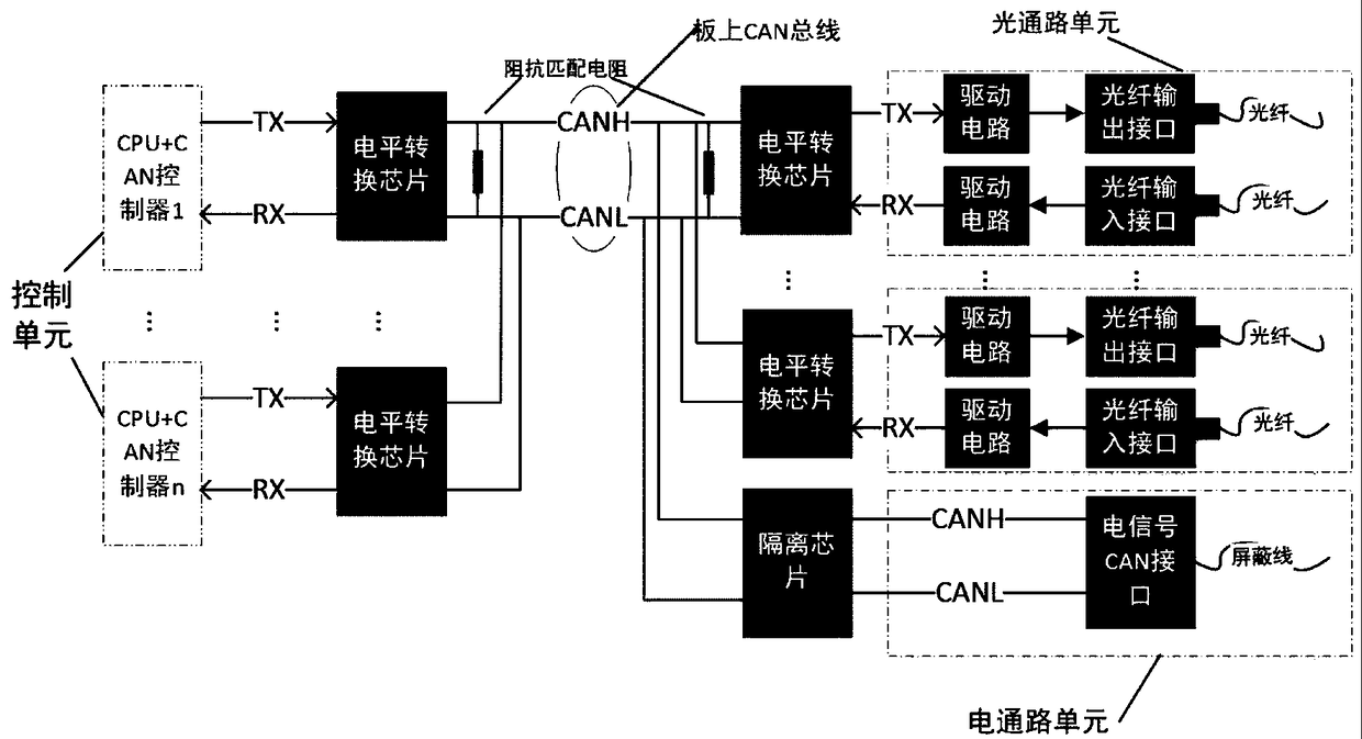
[0023] Such as image 3 As shown, the present invention discloses a local area network CAN bus control device, which is the basic unit of the entire local area network CAN network, including an optical path unit, an electrical path unit, a control unit, an impedance matching resistor, a CAN bus on the board, and a control side / Channel side level conversion chip, isolation chip, optical fiber input and output interface, electrical signal CAN interface controller, in which the optical channel unit, electrical channel unit, and control unit are parallel functional units, which can be flexibly configured ...


PUM


Abstract

The invention discloses an apparatus for controlling a CAN bus of an optical fiber local area network. The apparatus comprises an optical path unit, an electric path unit, a control unit, a impedance matching resistor, an on-board CAN bus, a level conversion chip, an isolation chip, an optical fiber input and output interface and an electric signal CAN interface; the optical path unit is provided with two interfaces: a receiving interface and a transmitting interface; the electric path unit is a standard electric signal CAN interface; the control unit comprises two parts: a CPU and a CAN controller; the on-board CAN bus is used for realizing a CAN networking function; the invention further discloses an application of the apparatus to accessing an optical fiber or an electric signal device for realizing the mutual connection of two local area network CAN bus control apparatuses, and for realizing the connection between two or more CAN local area networks; and the apparatus disclosed by the invention converts an externally accessed optical signal into an electric signal and connects the electric signal to the bus to realize the local area network type CAN bus so as to establish an interconnected optical fiber CAN network, the functions of an optical splitter are realized by the on-board CAN bus, and multiple paths of optical fiber interfaces and electric signal interfaces are compatible at the same time.

Description

technical field [0001] The invention belongs to the technical field of communication control, and in particular relates to an optical fiber local area network CAN bus control device and networking, which are mainly used in the establishment and connection expansion of the optical fiber local area network CAN bus. Background technique [0002] Most of the existing optical fiber LAN CAN bus technology is composed of two unidirectional transmission optical fibers to form a closed loop, such as figure 1 shown. [0003] In this way, each node has to go through the process of light-to-electricity-electricity-to-light, causing the delay to increase linearly with the increase in the number of nodes. [0004] In this way, the number of CAN nodes is limited under the requirements of CAN bus timing in the optical fiber LAN. [0005] In addition, in some applications, optical splitters are used to realize the interconnection of optical fibers, such as figure 2 As shown, although thi...

Claims


Application Information

Patent Timeline
Patent Type & Authority Patents(China)
IPC IPC(8): H04B10/25H04B10/278H04L12/40G05B19/418
CPCG05B19/41855G05B2219/1136H04B10/2589H04B10/278H04L12/40006H04L2012/40215Y02P90/02
Inventor 许晓晖赵晓宇梁宝明赵影张颖辉
Owner 中国船舶重工集团公司第七一二研究所
Learn More