
Ripple cancellation-based inductance DC-DC converter output ripple elimination technology

A technology of output ripple and DC-DC, which is applied in the direction of output power conversion device, DC power input conversion to DC power output, instruments, etc., can solve the problems of many limitations and increased structural complexity

Inactive Publication Date: 2017-02-01
NANJING UNIV OF AERONAUTICS & ASTRONAUTICS
View PDF5 Cites 2 Cited by
  • Summary
  • Abstract
  • Description
  • Claims
  • Application Information

AI Technical Summary

Problems solved by technology

For the two-phase interleaving technology, in order to ensure that the ripple can be effectively eliminated, there are relatively strict requirements on the switching duty cycle, which is more limited in actual use.
At the same time, multiple interleaving techniques can improve this situation, but the structural complexity will increase

Method used


Image

  • Ripple cancellation-based inductance DC-DC converter output ripple elimination technology
  • Ripple cancellation-based inductance DC-DC converter output ripple elimination technology
  • Ripple cancellation-based inductance DC-DC converter output ripple elimination technology

Examples


Embodiment Construction

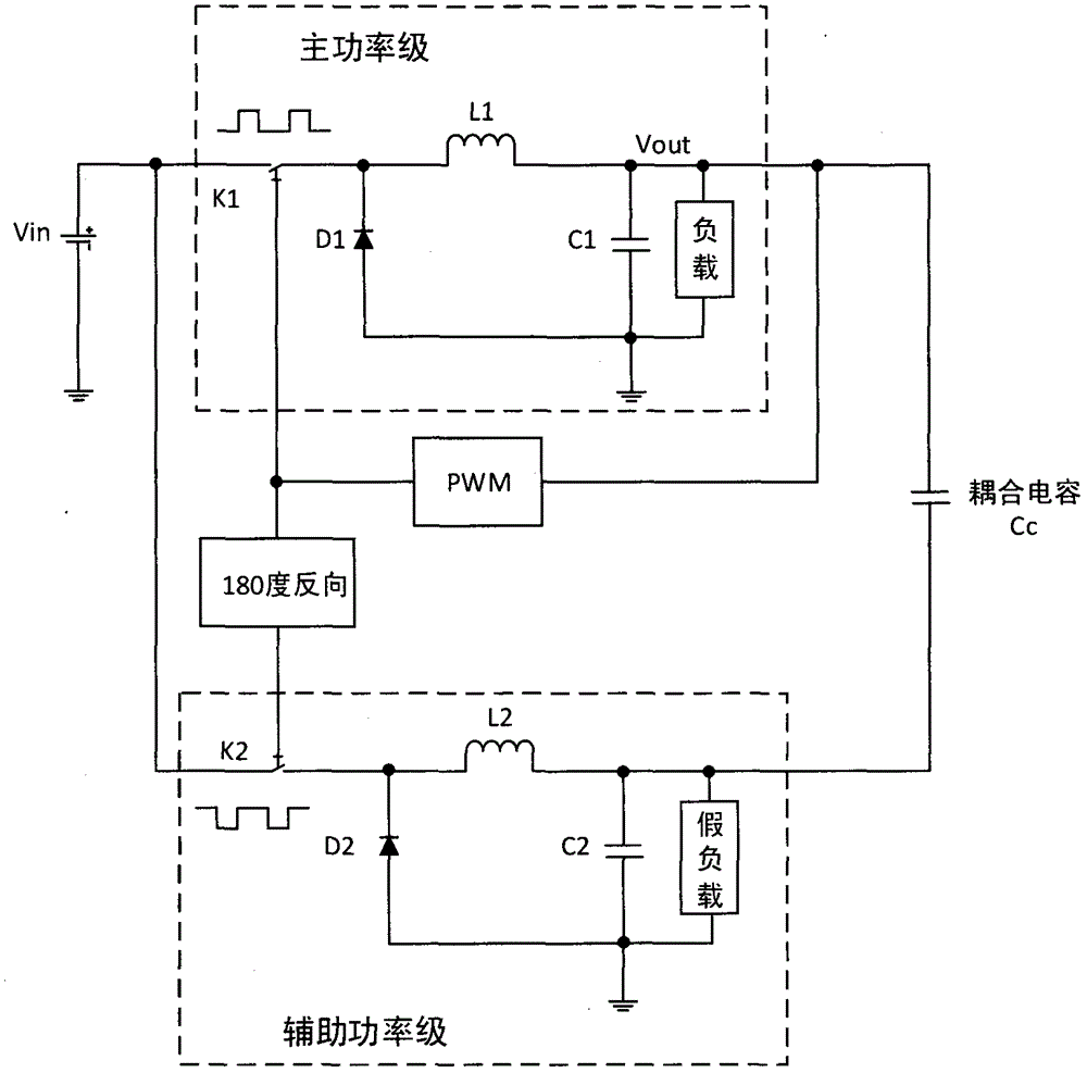
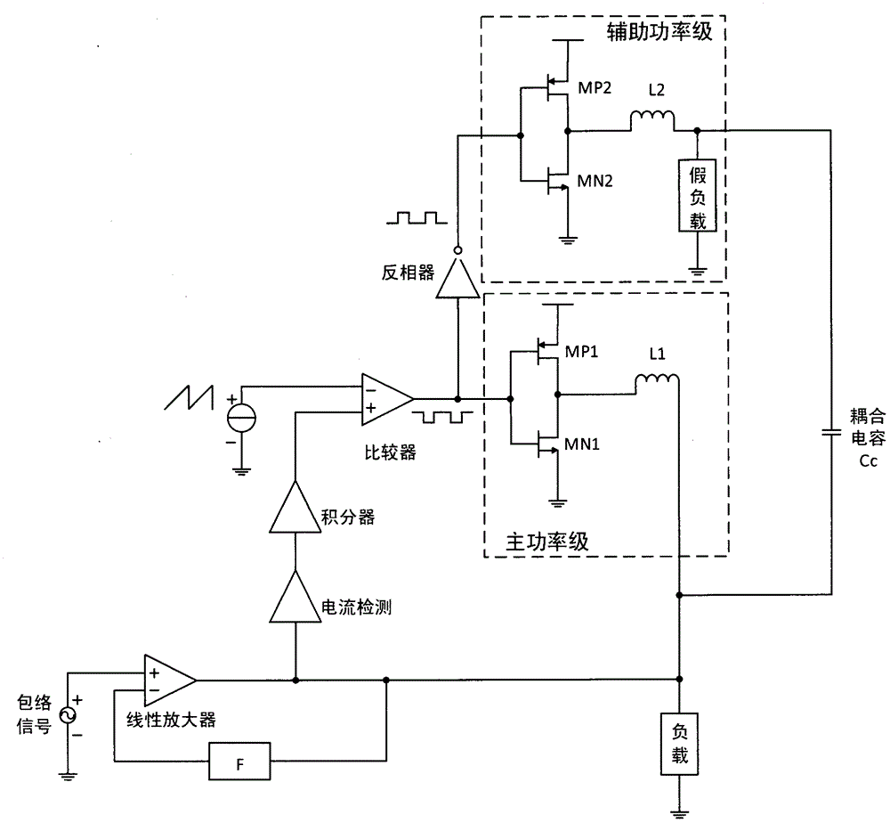
[0018] (1) In the DC-DC converter circuit, a copy of the power stage part of the switching power supply is introduced to form an auxiliary power stage. The load of the auxiliary power stage is a light load as a dummy load, and the inductance value should be equal to that of the main power stage.

[0019] (2) The control signal of the switch of the auxiliary power stage is reversely obtained through the control signal of the main power stage. At this time, the ripple generated by this part will be opposite to that of the ripple in the main circuit.

[0020] (3) Through capacitive coupling, the ripple of the auxiliary power stage is coupled to the load of the main circuit, so as to eliminate the output ripple.


PUM


Abstract

The invention provides a DC-DC converter output ripple elimination technology. According to the technology, a copy of a switch part is introduced as an auxiliary power stage in a DC-DC converter circuit; a pulse width modulation signal of which the logic polarity is opposite to that in a main circuit is adopted and a ripple of which the polarity is opposite to that of a primary circuit is generated; and the output ripple is finally eliminated at an output point of the main circuit through capacitive coupling.

Description

[0001] Technical field: [0002] The patent of the present invention proposes an implementation scheme for eliminating the output ripple of the DC-DC converter, and realizes the improvement of the efficiency of the switching power supply while taking into account the complexity of the structure. [0003] Background technique: [0004] With the development of modern communication technology, the appearance of a large number of portable devices has brought great convenience to people's life. In recent years, with the emergence of smart phones, tablet computers, and even similar smart bracelets and smart watches, wearable electronic products have also entered people's attention. These electronic products put forward higher requirements for battery life, and it is imperative to find a power supply technology with better performance. Due to the instability of the output of power supply equipment such as batteries, the power supply of electronic products is usually not directly prov...

Claims


Application Information

Patent Timeline
Patent Type & Authority Applications(China)
IPC IPC(8): H02M3/155H02M1/14
Inventor 卜刚王赛赛
Owner NANJING UNIV OF AERONAUTICS & ASTRONAUTICS
Learn More