
Real-time infrared simulation method based on thermal model

A simulation method and thermal model technology, applied in special data processing applications, instruments, electrical and digital data processing, etc., can solve the problems of backward program structure, difficult simulation results, improvement of infrared simulation technology, etc., to achieve easy engineering implementation, improve The effect of precision, simplified development and data management

Active Publication Date: 2017-02-01
中国人民解放军92728部队 +1
View PDF4 Cites 6 Cited by
  • Summary
  • Abstract
  • Description
  • Claims
  • Application Information

AI Technical Summary

Problems solved by technology

[0005] At present, the foreign commercial infrared simulation software available in China is mainly Vega, which is the early visual simulation product of Presagis, and has stopped updating Vega since 2001. The core of Vega is developed based on C language, and the program structure is backward. , does not provide support for new graphics hardware features. Its infrared simulation module is based on an infrared radiation calculation model. Through this model, the radiation amount of each surface element of the object is calculated, and the final quantitative output infrared simulation image is limited by the GPU at that time. The technology and computing work are all undertaken by the CPU, and a large amount of data is transmitted between the CPU and the GPU multiple times, which reduces the efficiency of infrared image generation; and in practice, it is found that the infrared module of the software has some technical defects and data errors , but because the source code of Vega software cannot be obtained, it is difficult to improve its infrared simulation technology, so it is difficult to obtain simulation results that meet the requirements by using this software

Method used


Image

  • Real-time infrared simulation method based on thermal model
  • Real-time infrared simulation method based on thermal model
  • Real-time infrared simulation method based on thermal model

Examples


Embodiment Construction

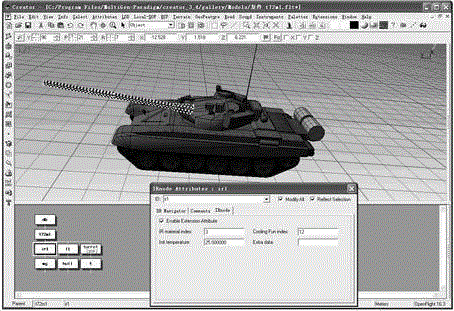
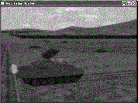
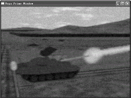
[0027] The following will combine Figure 1 ~ Figure 4 The thermal model-based real-time infrared simulation method of the present invention is further described in detail.

[0028]Infrared simulation is a simulation of the infrared radiation of the target and its propagation in the atmosphere and the energy conversion process in the detection equipment. In order to generate an infrared image that is basically consistent with the infrared detection system, the following aspects are mainly considered: (1) Establish the geometric model of the scene; (2) establish the thermal model of the target; (3) calculate the intrinsic radiance of the target surface; (4) use the atmospheric transmission software to calculate the atmospheric attenuation of the atmospheric path radiation and the infrared radiation of the target; (5) Consider the imaging effect of the optical system, and simulate the transmission characteristics of infrared radiation in the optical system; (6) simulate the char...


PUM


Abstract

The invention discloses a real-time infrared simulation method based on a thermal model. The method comprises the steps that an infrared material library is modeled, wherein a material temperature and an output level value of an infrared imaging system are measured, atmospheric radiation inversion and imaging effect inversion are carried out, and a corresponding relation between intrinsic radiance and the output level value of the infrared imaging system is established; a cooling function of a material is established, so that an infrared material description model of the material can be established; the infrared material library is established through testing and analysis of a series of materials; a storage format of an infrared thermal model is defined, wherein infrared characteristic parameters are stored in a geometric model through expansion of a storage format of the geometric model; and infrared effects are rendered, wherein the infrared characteristic parameters are read in synchronously during reading of the geometric model, thermal transmission effects, natural cooling courses and atmospheric transmission effects are simulated, and color control of the geometric model is achieved by fragment shader programming of GPU, so that verisimilar infrared simulation effects could be achieved finally.

Description

technical field [0001] The invention relates to a real-time infrared simulation technology, in particular to a thermal model-based real-time infrared simulation method. Background technique [0002] In recent years, infrared imaging systems have been greatly developed in the military and civilian fields. The applications in the civilian field such as monitoring systems, nighttime assisted driving, line inspection, personnel search and rescue, etc. are more widely used in the military, such as optical remote sensing, target Detection, night navigation and precision guidance, etc. Weapon systems using infrared imaging technology have the characteristics of high precision, little impact on climate, and flexible use. They have attracted close attention and vigorous development from various countries, and various weapon systems based on infrared imaging technology have been developed one after another. During the research and development of these weapon systems, it is often ne...

Claims


Application Information

Patent Timeline
Patent Type & Authority Applications(China)
IPC IPC(8): G06F17/50
Inventor 赵维谢晓方茅坪杨长胜
Owner 中国人民解放军92728部队
Learn More