
Pulse compression technique-based range imaging method and range imaging system

An imaging method and pulse compression technology, applied in the radio wave measurement system, radio wave reflection/re-radiation, utilization of re-radiation, etc., can solve the problems of imageable distance length limitation, limited application, and limited number of distance targets

Inactive Publication Date: 2017-02-01
SHANGHAI INST OF ELECTROMECHANICAL ENG
View PDF6 Cites 5 Cited by
  • Summary
  • Abstract
  • Description
  • Claims
  • Application Information

AI Technical Summary

Problems solved by technology

[0004] However, the existing adaptive pulse compression technology still has two problems: the imageable range length is limited by the length of the transmitted waveform and each iteration will reduce the range length of the imaging area
The existing adaptive pulse compression technology only uses a part of the received signal (the length is usually the length of the transmitted waveform) to update the weight vector, which belongs to the partial adaptive technology, and its adaptive freedom is limited by the length of the transmitted waveform. The number of targets is limited, so it cannot be used for large-scale scene imaging; in addition, this kind of adaptive pulse compression technology is at the cost of losing a certain length of range images at both ends in each iteration, and the range length of the imaging area increases with the number of iterations. The rapid decrease of the increase is equivalent to wasting a large part of the sampling data in the iterative process
These defects limit the practical application of the existing partial adaptive pulse compression technology

Method used


Image

  • Pulse compression technique-based range imaging method and range imaging system
  • Pulse compression technique-based range imaging method and range imaging system
  • Pulse compression technique-based range imaging method and range imaging system

Examples


Embodiment 1

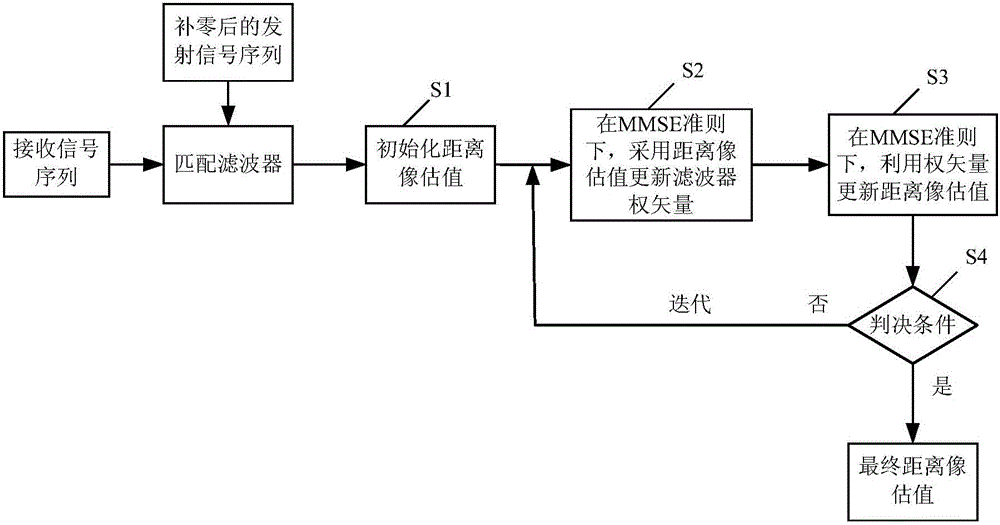
[0048] Such as figure 1 As shown, the present invention discloses a first embodiment of a range imaging method based on pulse compression technology of iterative full adaptive technology. The range imaging method includes the following steps:

[0049] S1. The received signal sequence of the matched filter and the transmitted signal sequence after zero padding. Range image initialization, using the transmitted signal sequence after zero padding sequence of received signals Perform matched filtering to obtain the initialized range image estimate

[0050] Assuming that the radar transmit waveform has a sampling length N, the irradiation area is composed of L distance units, the target backscatter coefficient of the lth distance unit is expressed as x(l), and the sampling length of the received signal of the radar receiver is not less than L+N- 1. In the first embodiment, the sampling length of the received signal is selected to be equal to L+N-1.

[0051] Considering the ...


PUM


Abstract

The present invention discloses a pulse compression technique-based range imaging method. The range imaging method includes the following steps that: a zero-filled transmitted signal sequence is adopted to carry out matched filtering on a received signal sequence, so that an initialized range image estimation value can be obtained; under the MMSE criterion, the existing range image estimation value is utilized to obtain a new filter weight vector; and the new filter weight vector is utilized to update the range image estimation value; and the above operation is executed repeatedly until a preset judgment condition is satisfied, so that range imaging is completed. According to the method, all received data are utilized to carry out the adaptive design of the filter weight vector; the degree of freedom of self-adaption is not limited by the length of transmitted signals; the range image of a target scene of any size can be estimated; and the estimated length of the range image in an iteration process will not be decreased. Compared with an existing method, the method has higher utilization rate of sampling data.

Description

technical field [0001] The invention relates to the technical field of radar signal processing, in particular to a range-direction imaging method and a range-direction imaging system based on pulse compression technology of iterative full self-adaptive technology. Background technique [0002] Pulse compression technology is widely used in radar imaging, ultrasonic detection and medical imaging. Pulse compression technology can enable the detection system to obtain a higher range resolution while maintaining a large average transmit power. Traditional pulse compression is accomplished by matched filters, but the range image obtained by matched filtering is often affected by high sidelobes and has limited resolution, so the application of matched filtering technology in pulse compression is limited. [0003] Adaptive pulse compression technology is a new pulse compression technology, the initial publication mainly includes: "IEEE Transactions on Aerospace and Electronic Syst...

Claims


Application Information

Patent Timeline
IPC IPC(8): G01S13/89
CPCG01S13/89
Inventor 马跃华陈义任继山花超孙全钟昭韦宇祥魏欣
Owner SHANGHAI INST OF ELECTROMECHANICAL ENG
Learn More