
an air duct machine

A technology of air duct machine and centrifugal fan, which is applied in space heating and ventilation, heating methods, lighting and heating equipment, etc. It can solve problems such as easy to generate abnormal vibration, abnormal sound, and reduce user experience

Active Publication Date: 2019-10-11
HISENSE (SHANDONG) AIR CONDITIONING CO LTD
View PDF5 Cites 0 Cited by
  • Summary
  • Abstract
  • Description
  • Claims
  • Application Information

AI Technical Summary

Problems solved by technology

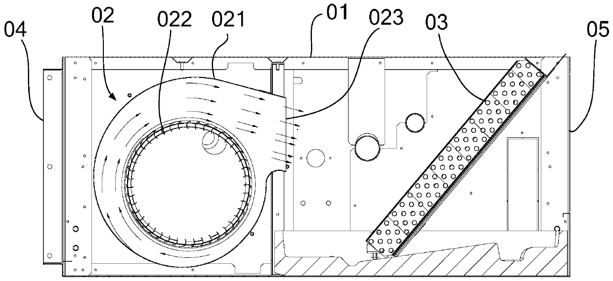
[0004] In the process of realizing the above-mentioned air duct machine, the inventor found that there are at least the following problems in the prior art: since the air outlet 023 of the volute 021 is opposite to the evaporator 03, when the wind blows out from the air outlet 023 of the volute 021, especially The wind speed at the tangent line of the outer edge of the impeller 022 is very fast and has a certain static pressure. When the wind blows directly to the evaporator 03 and passes through the fins, the fins of the evaporator 03 are easily blown under the action of high wind pressure and high wind speed. Abnormal vibrations are generated, resulting in abnormal sounds, which degrades the user experience

Method used


Image

  • an air duct machine
  • an air duct machine
  • an air duct machine

Examples


Embodiment Construction

[0013] The technical solutions in the embodiments of the present invention will be clearly and completely described below in conjunction with the accompanying drawings in the embodiments of the present invention. Obviously, the described embodiments are only a part of the embodiments of the present invention, rather than all the embodiments. Based on the embodiments of the present invention, all other embodiments obtained by those of ordinary skill in the art without creative work shall fall within the protection scope of the present invention.

[0014] In the description of the present invention, it should be understood that the terms "center", "upper", "lower", "front", "rear", "left", "right", "vertical", "horizontal", The orientation or positional relationship indicated by "top", "bottom", "inner", "outer", etc. are based on the orientation or positional relationship shown in the drawings, and are only for the convenience of describing the present invention and simplifying the...


PUM


Abstract

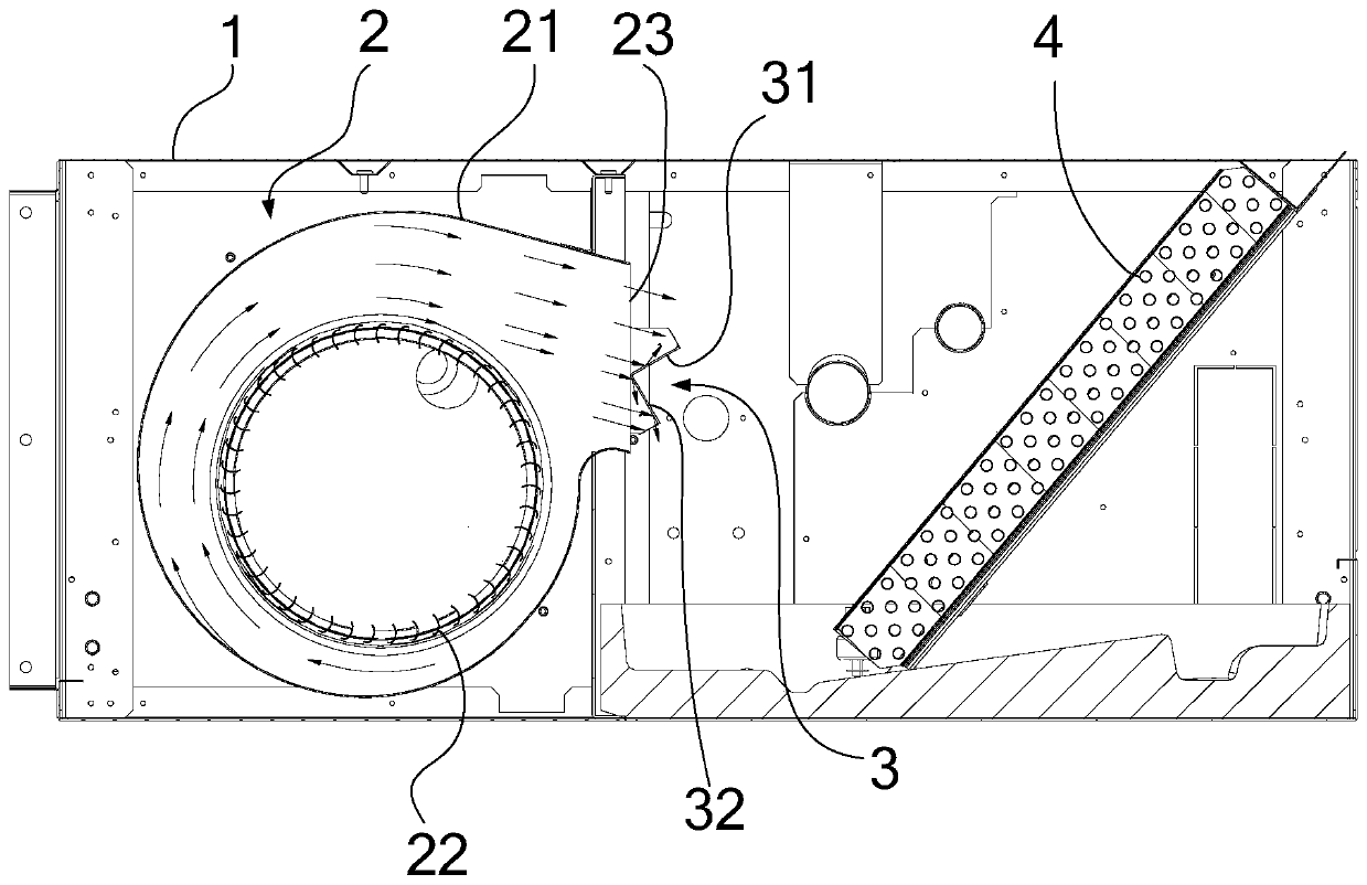
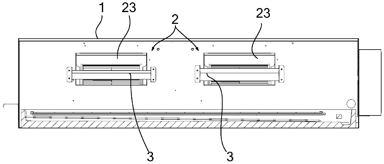
The invention discloses a wind pipe machine and relates to the technical field of air conditioners. The wind pipe machine is invented for solving the problem that in the prior art, when a wind pipe machine works, fins of an evaporator produce abnormal sounds. The wind pipe machine comprises a machine shell. A centrifugal fan and an evaporator are arranged in the machine shell. The centrifugal fan comprises a volute and an impeller arranged in the volute. An air outlet of the volute is opposite to the evaporator. A flow guide bar is arranged at the position of the air outlet of the volute, and the extending direction of the flow guide bar is parallel to the rotating center line of the impeller. At least one part of the flow guide bar is located on the air outlet route tangent to the edge of the impeller. The wind pipe machine can be used for air conditioner indoor units.

Description

Technical field [0001] The invention relates to the technical field of air conditioners, in particular to a duct machine. Background technique [0002] The air duct machine is a new model developed in response to the diverse needs of the market and the changes in the overall decoration space. It is suitable for occasions with small installation and maintenance widths, especially for small-sized households. Nowadays, users have higher and higher requirements for reducing their noise. Because the household sky-buried air duct is installed in the bedroom, it is more necessary to effectively control the noise level of the air duct machine, and no abnormal noise is allowed, so as to achieve complete silence. effect. [0003] The existing air duct machine is such as figure 1 The structure shown includes: a casing 01, a centrifugal fan 02 and an evaporator 03 are arranged in the casing 01, the centrifugal fan 02 includes a volute 021 and an impeller 022 arranged in the volute 021, and th...

Claims


Application Information

Patent Timeline
Patent Type & Authority Patents(China)
IPC IPC(8): F24F1/0022F24F13/08F24F13/24
Inventor 王世科
Owner HISENSE (SHANDONG) AIR CONDITIONING CO LTD
Learn More