
cutting machine

A cutting machine and cutting technology, which are applied in the cutting of textile materials, textile and papermaking, metal processing, etc., can solve problems such as difficulty in correction, and achieve the effects of reducing the inflow of air, reducing costs, and preventing the drop of suction pressure.

Inactive Publication Date: 2018-05-29
SHIMA SEIKI MFG LTD
View PDF9 Cites 0 Cited by
  • Summary
  • Abstract
  • Description
  • Claims
  • Application Information

AI Technical Summary

Problems solved by technology

If the output of the blower that generates suction pressure is increased, correction can be made to make up for the decrease in suction pressure to some extent, but if cutting is performed and the number of cut parts increases, correction will become difficult.

Method used

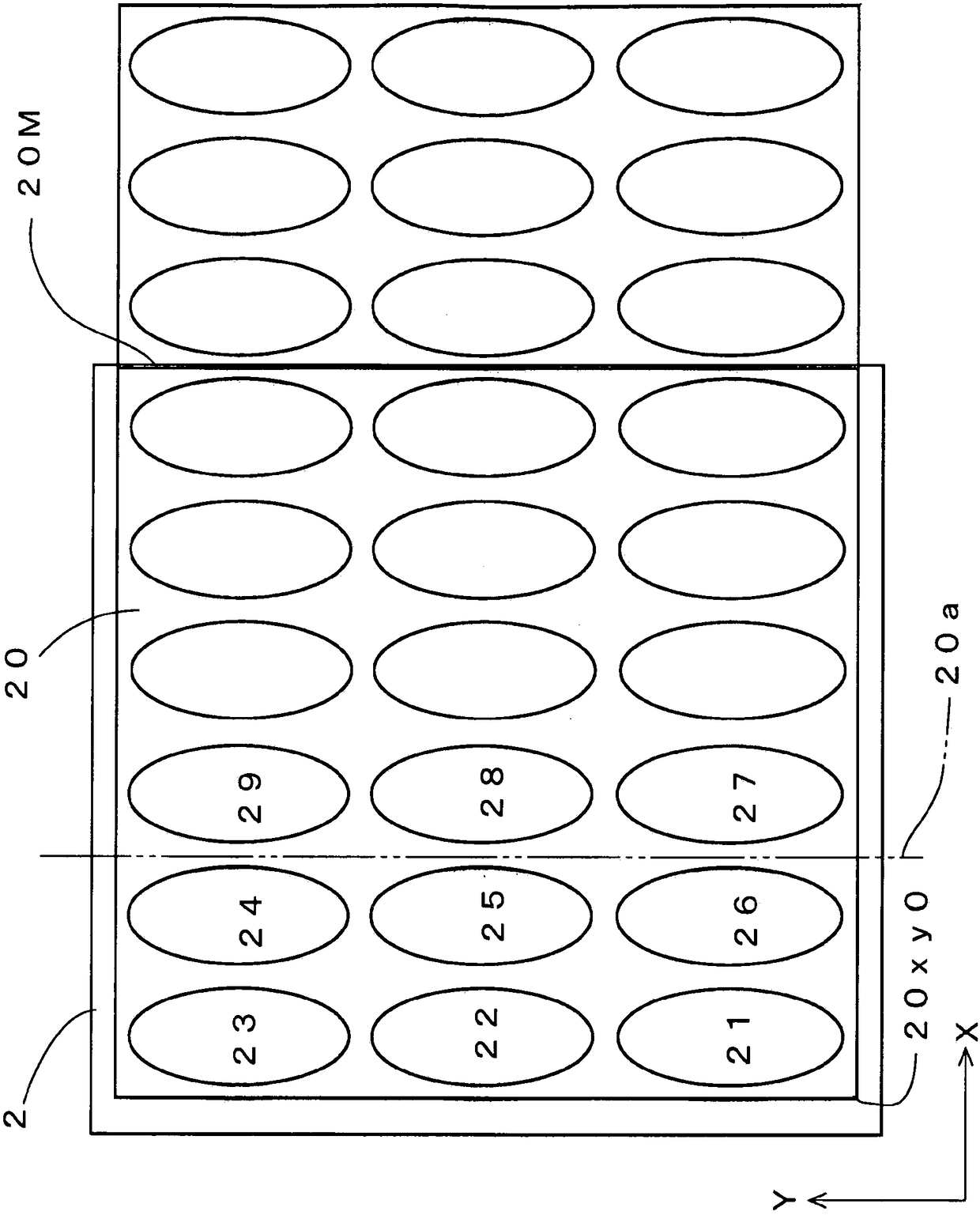
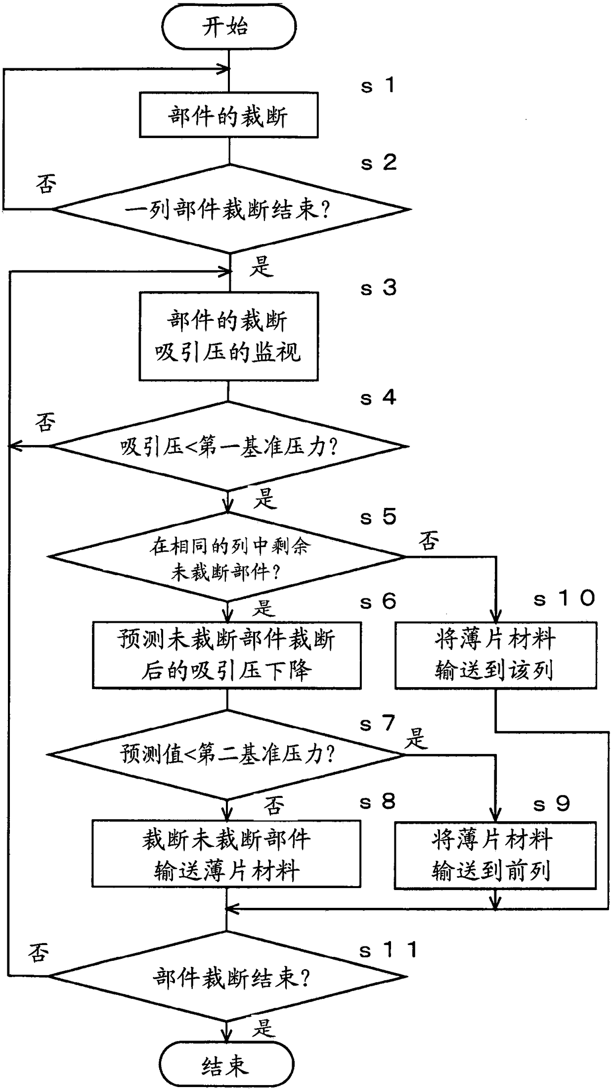

Image

  • cutting machine
  • cutting machine
  • cutting machine

Examples


Embodiment

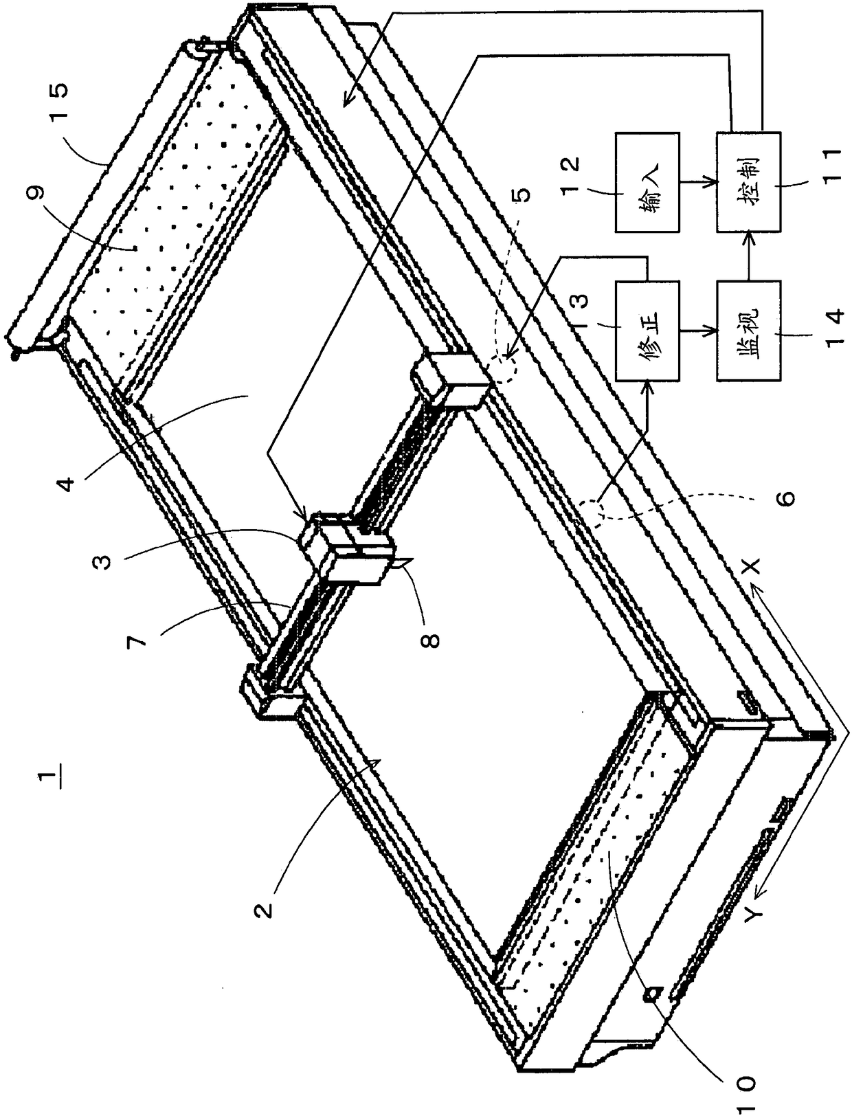
[0032] figure 1The schematic structure of the cutting machine 1 which is one Example of this invention is shown. The cutting machine 1 includes a cutting table 2 and a cutting head 3 . The cutting table 2 has a function of attracting and fixing a sheet material covered with an airtight sheet for cutting a plurality of parts. The cutting head 3 moves along the surface of the cutting table 2 . The surface of the cutting table 2 is formed of an air-permeable bristle brush or felt as a conveyor belt 4, which can convey stacked sheet materials. In the cutting table 2 , a blower 5 is provided below the conveyor belt 4 to suck air and suck the sheet material covered with the airtight sheet toward the surface of the conveyor belt 4 . A sensor 6 is provided below the conveyor belt 4 in order to detect the suction pressure. The Y beam 7 travels along the surface of the conveyor belt 4 in the X-axis direction serving as the conveyance direction, and extends in the Y-axis direction pe...


PUM


Abstract

The present invention provides a cutting machine capable of reducing the energy and cost required for the generation of the suction pressure even without using a sheet laid on the upper surface. The control assembly (11) of the cutting machine (1), as a control for preventing the suction pressure from dropping, if the suction pressure monitored by a monitoring unit (14) is decreased compared with the reference pressure, automatically performs control like that a sheet material of the cut-off portion of at least a part of a cutting member is conveyed to the output side of a cutting table (2). It is possible to reduce the inflow air so that the suction pressure does not decrease as compared with the reference pressure even if the cut member is not covered by the sheet covering the upper sheet.

Description

technical field [0001] The present invention relates to a cutting machine which cuts a sheet material on a cutting table and cuts out a plurality of parts from the sheet material. Background technique [0002] In the past, when cutting a sheet material such as air-permeable cloth by a cutting machine, the surface of the laminated sheet material is covered by an airtight sheet, and the sheet material is fixed on the cutting table by suction from the bottom of the cutting table (for example, refer to the patent document 1). The cutting table has a conveying function. The sheet material covered by the airtight sheet is input by conveying, the conveying is stopped during cutting, and the conveying is resumed after cutting to output the sheet material. In the cutting of the sheet material, the outer shape of each part is cut by a cutting blade provided on a cutting head which moves two-dimensionally along the X-axis and Y-axis along the surface of the cutting table. The cutting...

Claims


Application Information

Patent Timeline
Patent Type & Authority Patents(China)
IPC IPC(8): B26D7/01B26D5/00D06H7/00
CPCB26D5/005B26D7/015B26D7/018D06H7/00
Inventor 前上雅彦
Owner SHIMA SEIKI MFG LTD
Learn More