Sealed automatic feeding compounding tank

An automatic feeding and sealing technology, which is used in mixer accessories, mixers with rotary stirring devices, and dissolving directions, can solve the problems of waste of raw materials, pollute the environment, and be prone to falls, and reduce the workload and the environment. The effect of pollution and production cost saving

Inactive Publication Date: 2017-02-01
张庭辉
View PDF0 Cites 1 Cited by
  • Summary
  • Abstract
  • Description
  • Claims
  • Application Information

AI Technical Summary

Problems solved by technology

[0002] The production of waterproof materials often requires batching. The batching of traditional technology is carried out in a special batching workshop. When batching, workers need to weigh the required raw materials first, and then lift the heavy material bag to dump the material in the bag. In the above process, because the particles of the raw materials are relatively light, dust will inevitably be generated during the dumping process of the raw materials, and the raised particles will be scattered around, which may not only pollute the environment, but also cause harm to the health of the staff. Adverse effects. The batching tank is usually more than 5 meters high. It is not only difficult, time-consuming and laborious for workers to carry materials, but also prone to dangers such as falling. At present, the feeding port of the existing batching tank is located on the top of the batching tank, and the raw materials enter from top to bottom In the batching tank, since the dust collector is also located on the top of the batching tank, the dust collector will suck a part of the raw materials out of the tank when loading materials, which not only causes waste of raw materials, but also increases the workload of the dust collector and affects the service life of the dust collector; if Turning off the dust collector when loading materials will not achieve a good dust removal effect, and the floating raw material dust will pollute the working environment of the batching workshop

Method used


Image

  • Sealed automatic feeding compounding tank

Examples


Embodiment Construction

[0012] The following will clearly and completely describe the technical solutions in the embodiments of the present invention with reference to the accompanying drawings in the embodiments of the present invention. Obviously, the described embodiments are only some, not all, embodiments of the present invention. Based on the embodiments of the present invention, all other embodiments obtained by persons of ordinary skill in the art without making creative efforts belong to the protection scope of the present invention.

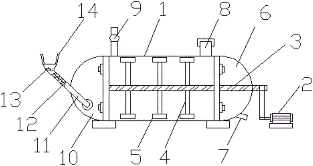
[0013] see figure 1 , the present invention provides a technical solution: a sealed automatic feeding batching tank, including a device main body 1, a gear motor 2, a stirring shaft 3, a stirring blade 4, a blade scraper 5, a right cover 6, an outlet Material port 7, observation port 8, exhaust gas collection tube 9, left cover 10, material conveying pipe 11, screw conveying shaft 12, material inlet 13 and material conveying branch pipe 14, the right side of t...


PUM


Abstract

The invention discloses a sealed automatic feeding compounding tank. The sealed automatic feeding compounding tank comprises a device body, a gear motor, a stirring shaft, stirring blades, blade scrapers, a right sealing cover, a discharge opening, an observation opening, a waste gas collection barrel, a left sealing cover, a material conveying pipeline, a spiral conveying shaft, a feed opening and a plurality of material conveying branch pipes, wherein the gear motor is arranged on the right side of the device body; the upper side of the gear motor is connected with the stirring shaft; the stirring blades are arranged on the upper side and the lower side of the stirring shaft; the blade scrapers are arranged at the tail ends of the stirring blades; the right side of the device body is connected with the right sealing cover; the discharge opening is formed in the lower side of the right sealing cover; the observation opening is formed in the upper side of the device body; the waste gas collection barrel is arranged at the left side of the observation opening. The sealed automatic feeding compounding tank has the characteristics of being safe and environment-friendly and saving raw materials; the feeding opening is formed in the bottom of the tank body; the raw materials are pushed by a material conveying main pipe with the spiral conveying shaft; the material conveying branch pipes are arranged to bring convenience for adding different types and amounts of the raw materials.

Description

technical field [0001] The invention relates to an automatic feeding batching device in the mechanical field, in particular to a sealed automatic feeding batching tank. Background technique [0002] The production of waterproof materials often requires batching. The batching of traditional technology is carried out in a special batching workshop. When batching, workers need to weigh the required raw materials first, and then lift the heavy material bag to dump the material in the bag. In the above process, because the particles of the raw materials are relatively light, dust will inevitably be generated during the dumping process of the raw materials, and the raised particles will be scattered around, which may not only pollute the environment, but also cause harm to the health of the staff. Adverse effects. The batching tank is usually more than 5 meters high. It is not only difficult, time-consuming and laborious for workers to carry materials, but also prone to dangers su...

Claims


Application Information

Patent Timeline
IPC IPC(8): B01F7/04B01F15/00B01F15/02
CPCB01F27/17B01F27/191B01F27/70B01F35/123B01F35/181B01F35/71705B01F35/7163
Inventor 张庭辉
Owner 张庭辉
Why Eureka
Try Eureka