
A holographic stereo speaker

A loudspeaker and stereo technology, applied in the direction of electrostatic transducer speakers, sensors, electrical components, etc., can solve the problem that the speaker cannot realize holographic stereo playback

Active Publication Date: 2019-06-11
陈立康 +2
View PDF9 Cites 0 Cited by
  • Summary
  • Abstract
  • Description
  • Claims
  • Application Information

AI Technical Summary

Problems solved by technology

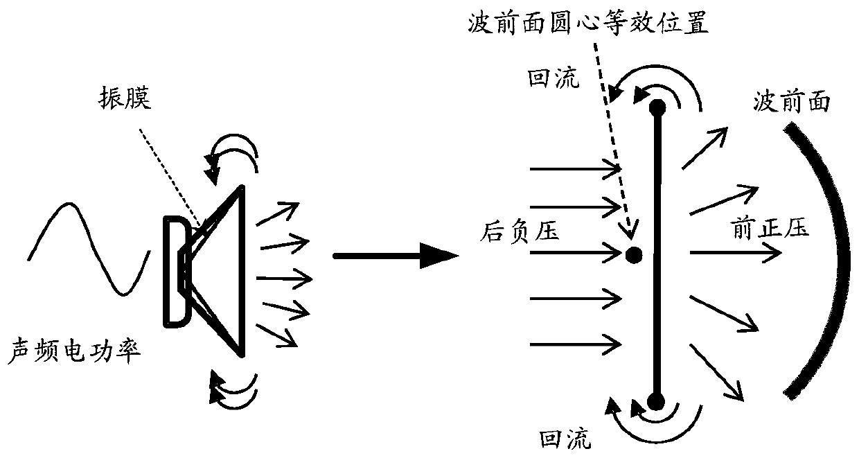
[0018] The invention provides a holographic stereo speaker to at least solve the problem that the speaker in the prior art cannot realize holographic stereo playback

Method used


Image

  • A holographic stereo speaker
  • A holographic stereo speaker
  • A holographic stereo speaker

Examples


Embodiment 1

[0067] In this embodiment, the finished product is used to assemble the holographic three-dimensional moving coil speaker. A hollow spherical box made of speaker material is opened with a circular hole in the space equalizing four-vector position, and four traditional full-band high-compliance speakers are installed in the circular hole. Above, forming a closed space. The definition of directionality is the same as the above example. This embodiment can be realized by assembling existing finished speakers, which is easy to manufacture. Since the inner space is closed, there is a strong elastic "damping" for vibration (in fact, the conversion of sound power), the relationship between the volume of the cabinet and the frequency should be considered during production. A larger volume has a lower resonance frequency. If you reduce the original The speaker's voice coil support (bouncing waves) and the damping of the paper cone edge structure (that is, increase the compliance) can f...

Embodiment 2

[0069] Figure 15 Is a schematic diagram of a first structure of a holographic stereo dynamic speaker according to an embodiment of the present invention, Figure 16 It is a schematic diagram of the second structure of the holographic stereo dynamic speaker according to the embodiment of the present invention, such as Figure 15 with Figure 17 As shown, the traditional speaker basin frame is changed from a conical shape to a shallow basin regular triangle, and the four speaker basin frames can be assembled to obtain a regular tetrahedral structure. No ventilation gaps are left at the joint of the basin frame. The magnetic circuit structure can be installed inside or outside. The cone design has also changed from a cone to a triangular shallow cone. The voice coil bracket and cone edge adopt high-compliance structure. A suitable lead bracket is reserved on the holographic three-dimensional dynamic speaker. After assembly, a stable fixed bracket ( Figure 15 A straight line bet...


PUM


Abstract

The invention discloses a holographic stereo loudspeaker. The holographic stereo loudspeaker comprises multiple loudspeaker bodies and a supporting structure, wherein the supporting structure is used for supporting the multiple loudspeaker bodies, so that equivalent working surfaces of the multiple loudspeaker bodies are located on one surface of a regular polyhedron, and the center of the equivalent working surface of each loudspeaker body coincides with the center of the surface corresponding to the equivalent working surface. According to the holographic stereo loudspeaker, the sound wave strength and phase generated in each direction are different, a function of playing back sound source wave fields in single-point positions in upper, lower, left, right, front and back directions is realized, real direction features of field wave fields can be simulated in a certain range, more than two holographic stereo sound playing systems can generate a larger range of physical sound fields, so that the stereo sound effect is realized. The holographic stereo audio technology adopts physical imaging and out-of-ear imaging and can realize a stereo audio effect which do not change with listening positions and postures and has left, right, high, low and depth three-dimensional space expression. The holographic stereo loudspeaker is the representation technology of field physical sound field and is applied to the final link of the holographic stereo audio technology.

Description

Technical field [0001] The present invention relates to the technical field of sound, in particular to a holographic stereo speaker. Background technique [0002] When audio realizes stereoscopic sound imaging, there are two ideas of simulating biological sensory imaging and physical wave field reproduction. [0003] The biological sensory imaging method is to simulate the difference of the wave field between the two ears of the human body, so that the brain can get the feeling of the sound source position. The current technology is mainly realized by the difference between the left and right volume, but in fact, it has not really realized the reproduction of the wave field. At present, there is a head-mounted holographic sound technology that simulates the sound field around the human head to realize the front, back, left, and right pickup and playback. However, the listener must wear the headset to have the holographic sound (full surround sound technology) effect, which is easy...

Claims


Application Information

Patent Timeline
Patent Type & Authority Patents(China)
IPC IPC(8): H04R9/08H04R19/02
CPCH04R9/08H04R19/02
Inventor 陈立康陈雯箐吴小洲
Owner 陈立康
Learn More