Bearing chamber, motor enclosure having same and motor
A bearing chamber and housing technology, applied in the direction of the housing/cover/support, electrical components, electromechanical devices, etc., can solve the problems of damage to the bearing matching process, low production efficiency, bearing creep, etc., to achieve uniform force and production. High efficiency and anti-creep effect
- Summary
- Abstract
- Description
- Claims
- Application Information
AI Technical Summary
Problems solved by technology
Method used
Image

Examples
Embodiment 1
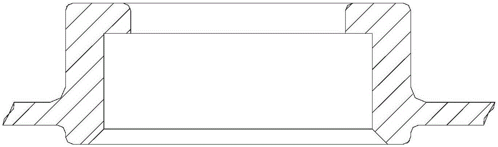
[0047] This embodiment provides a bearing chamber, such as Figure 4 As shown, the bearing chamber 4 is cylindrical, the inside of which is a cavity, and the end face has an opening, and the diameter of the opening is smaller than the inner diameter of the cavity. When in use, the bearing 3 is installed in the bearing chamber. cannot come out of the opening.
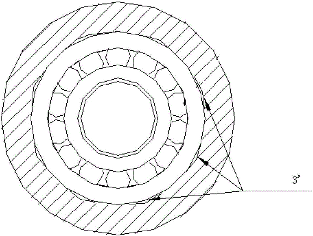
[0048] Such as Figure 4 As shown, the inner wall surface of the bearing chamber 4 is provided with a recess 5, such as Figure 5 , 6 As shown, the concave portion 5 is provided with an elastic body 6 , and the elastic body 6 radially protrudes from the inner wall surface of the bearing chamber 4 .
[0049]The above-mentioned bearing chamber 4 has a concave portion 5 on its inner wall surface, and the elastic body 6 is placed in the concave portion 5, and the elastic body 6 protrudes from the inner wall surface. Since the recess 5 is provided on the inner surface of the bearing chamber, the bearing chamber 4 and the ...
Embodiment 2
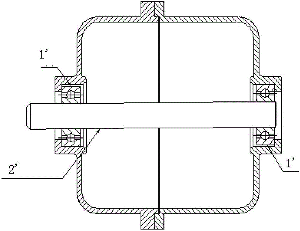
[0058] This embodiment provides a motor casing, such as Figure 7 As shown, the motor casing 1 is formed by butting the first casing 11 and the second casing 12, and the butt surface of the first casing 11 and the second casing 12 extends along the vertical direction, and also That is, the first casing 11 and the second casing 12 are arranged along the left-right direction, so as to form a joint surface in the vertical direction.
[0059] Here, it should be noted that the abutting surfaces of the first casing 11 and the second casing 12 extend along the vertical direction, which does not mean that the abutting surfaces of the two are completely vertical, but only that the first casing 11 and the second cabinet 12 are arranged along the left-right direction in the horizontal direction.
[0060] Such as Figure 7 As shown, the first casing 11 has a flange at the abutting surface, and the second casing 12 has a groove at the abutting surface, and the flange fits exactly with th...
Embodiment 3
[0065] This embodiment provides a motor, including a motor casing 1, a bearing 3 installed in the bearing chamber 4 of the motor casing 1, and a rotating shaft 2, and the rotating shaft 2 extends into the bearing chamber 4 and is connected with the bearing chamber 4. The bearing 3 is matched, and the bearing chamber 4 is any one of the bearing chambers described in Embodiment 1.
[0066] Such as Figure 7 , 8 As shown, the inner wall surface of the above-mentioned bearing chamber 4 is provided with a concave portion 5, and the elastic body 6 is placed in the concave portion 5, and the elastic body 6 protrudes from the inner wall surface. Since the recess 5 is provided on the surface of the inner wall of the bearing chamber, the bearing chamber 4 and the bearing 3 can be designed according to the clearance fit size of the base hole system, so that when the bearing 3 is installed into the bearing chamber 4, it is not necessary to heat the bearing chamber 4, and the bearing can ...
PUM
 Abstract
Description
Claims
Application Information
 - R&D
- Intellectual Property
- Life Sciences
- Materials
- Tech Scout
- Unparalleled Data Quality
- Higher Quality Content
- 60% Fewer Hallucinations
Browse by: Latest US Patents, China's latest patents, Technical Efficacy Thesaurus, Application Domain, Technology Topic, Popular Technical Reports.
© 2025 PatSnap. All rights reserved.Legal|Privacy policy|Modern Slavery Act Transparency Statement|Sitemap|About US| Contact US: help@patsnap.com