Visualization method of load transfer path of bearing structure based on the principle of stiffness change

A load-bearing structure and stiffness change technology, applied in the direction of electrical digital data processing, special data processing applications, instruments, etc., can solve the problems of unequal size, inability to accurately describe the transmission path, etc., and achieve the effect of clear configuration

Active Publication Date: 2019-04-09
XI AN JIAOTONG UNIV
View PDF2 Cites 0 Cited by
  • Summary
  • Abstract
  • Description
  • Claims
  • Application Information

AI Technical Summary

Problems solved by technology

The principal stress trace method is currently the most widely used method for extracting load paths. It is widely used in the reinforcement of concrete structures and the shape design of structures. The stress at each point on the principal stress trace has the same properties, but its The magnitudes are generally not equal, and in general the principal stress trace is not connected from the point of application of the load to the point of restraint, these properties of the principal stress trace make it impossible to accurately describe the transfer path of the load within the structure

Method used


Image

  • Visualization method of load transfer path of bearing structure based on the principle of stiffness change
  • Visualization method of load transfer path of bearing structure based on the principle of stiffness change
  • Visualization method of load transfer path of bearing structure based on the principle of stiffness change

Examples


Embodiment Construction

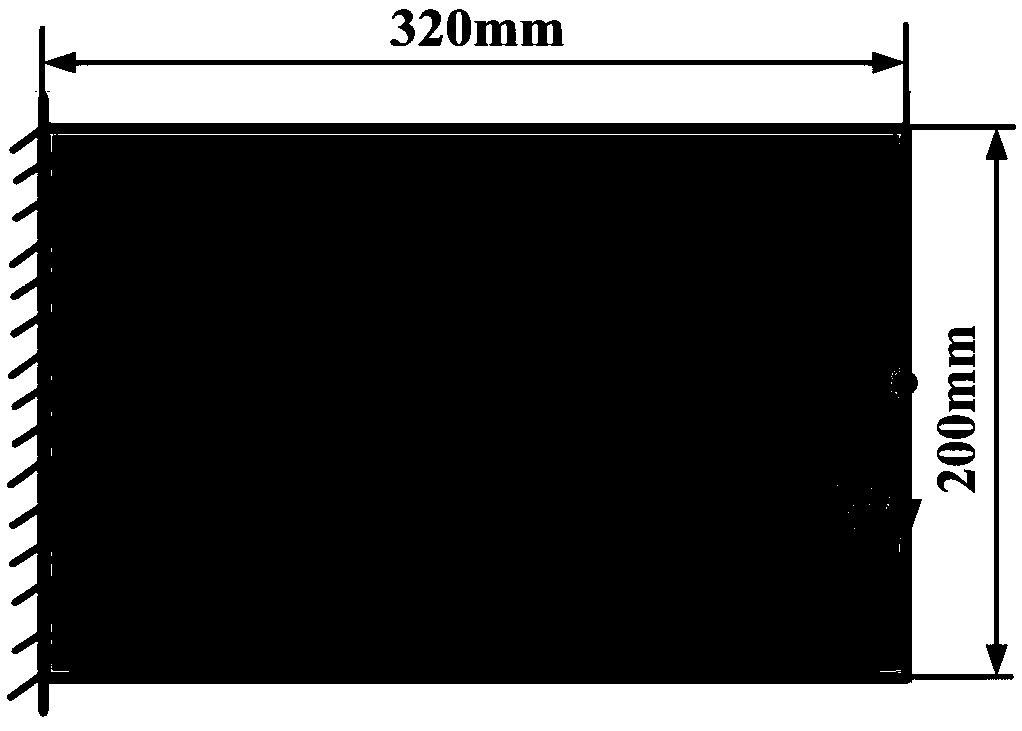
[0027] In the following, the present invention will be further described in conjunction with the embodiment of the visualization of the load path when the cantilever beam structure of 320mm*200mm*5mm is loaded.

[0028] A method for visualizing the load transfer path of a bearing structure based on the principle of stiffness variation, including the following steps:

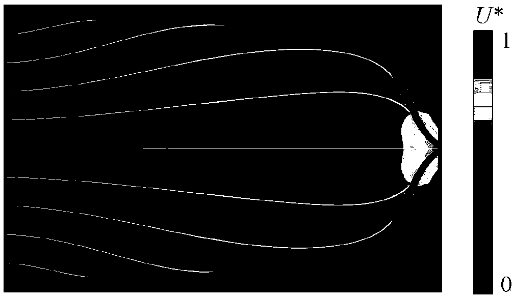
[0029] 1) Solve the U* field of the load-bearing structure: use the finite element method to model the cantilever beam structure, apply constraints and loads, and calculate the U* value of each node in the load-bearing structure, and then obtain the U* field by interpolation. The method of solving the U* value of a certain point in the structure is as follows:

[0030]

[0031] In the formula, U is the strain energy of the load-bearing structure under the original constraints and loads; U' is the structural strain energy of the load-bearing structure after adding full constraints to the target point on the bas...


PUM


Abstract

The load transfer path visualization method of load-bearing structures based on the principle of stiffness change first calculates the U* of each point in the load-bearing structure and its corresponding gradient vector, and uses the fourth-order Runge-Kutta numerical integration method to calculate the U* of each point in the load-bearing structure The gradient vector is numerically integrated, and the obtained curve is the load path in the load-bearing structure; then, starting from the point where U* is zero, the U* field contour is extracted, and the cross-section is made for each point on the contour along each contour analysis, extract the ridge points on it, and connect each ridge point in sequence to obtain the main load path based on the stiffness change; the invention can clarify the transfer direction and distribution form of the load path in the structure, in order to accurately grasp the load transfer and distribution rules.

Description

technical field [0001] The invention belongs to the technical field of load-bearing structure design, and in particular relates to a load-transfer path visualization method of a load-bearing structure based on the principle of stiffness variation. technical background [0002] The load-bearing structure is an important basic component of industrial equipment, and its main function is to support other parts and transfer loads. In the structural design stage, the visualization of the load path is also of great help to the evaluation of the structural load-bearing performance and the optimal use of materials. The principal stress trace method is currently the most widely used method for extracting load paths. It is widely used in the reinforcement of concrete structures and the shape design of structures. The stress at each point on the principal stress trace has the same properties, but its The magnitudes are generally not equal, and in general the principal stress trace is n...

Claims


Application Information

Patent Timeline
Patent Type & Authority Patents(China)
IPC IPC(8): G06F17/50
CPCG06F30/13
Inventor 李宝童杨梓辉刘宏磊田向阳洪军
Owner XI AN JIAOTONG UNIV
Why Eureka
Try Eureka