
Following type driving speed reducer

A follow-up, reducer technology, applied in mechanical equipment, transmission devices, differential transmission devices, etc., can solve the problems of low machining accuracy of transmission parts, unstable transmission, poor stability, etc., to eliminate design defects, transmission Smooth and reliable effect with low mechanical wear rate

Active Publication Date: 2017-01-25
HSOAR GRP
View PDF4 Cites 20 Cited by
  • Summary
  • Abstract
  • Description
  • Claims
  • Application Information

AI Technical Summary

Problems solved by technology

The defects and deficiencies of this type of mechanical transmission reducer are: due to the low machining accuracy of the transmission parts, there is a certain process gap in the design and installation process of the gear or worm gear reducer, which affects the output accuracy. The movement between them is in the form of a high pair, which is prone to problems such as mechanical wear, unstable transmission, loud noise, and poor output accuracy.
However, the driving ball is prone to slight jumps when working, and its stability is poor, and it is easy to produce unsmooth output of the reducer, stepping vibration, high wear rate, etc.

Method used


Image

  • Following type driving speed reducer
  • Following type driving speed reducer
  • Following type driving speed reducer

Examples


Embodiment Construction

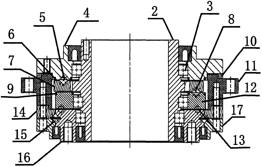
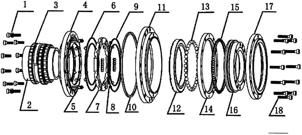
[0016] The present invention will be further described in detail below in conjunction with the accompanying drawings and specific embodiments.

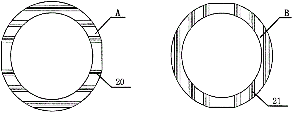
[0017] see Figure 1 to Figure 6 , the present invention is applied to a follow-up drive reducer for joint robots, including an input shaft 2, an output shaft 16, a body shell 11, a rear pressure plate 4, a differential transmission 12, a bearing upper cover 14, and a bearing lower cover 17. A follower plate 7 is installed between the differential transmission 12 and the rear pressure plate 4, and the A surface of the follower plate 7 is provided with an A surface V-shaped track 20 (multiple parallel, also known as A surface V-shaped grooves). There are first cross rollers 5 (several), and its B surface is provided with B surface V-shaped tracks 21 (multiple parallel, also known as B surface V-shaped grooves) equipped with second cross rollers 8 (several ); the rear platen 4 is provided with a transmission track 22 for installing the...


PUM


Abstract

The invention relates to a following type driving speed reducer for a joint robot. The following type driving speed reducer comprises an input shaft (2), an output shaft (16), a machine casing (11), a back press plate (4), a differential gearbox (12), a bearing upper cover (14), and a bearing lower cover (17), wherein a following plate (7) is arranged between the differential gearbox and the back press plate; a V-shaped rail (20) of a surface A is arranged on the surface A of the following plate, a V-shaped rail (21) of a surface B is arranged on the surface B of the following plate, a first crossing roller (5) is arranged on the V-shaped rail (20), and a second crossing roller (8) is arranged on the V-shaped rail (21); a transmission track (22) for installing the first crossing roller is arranged on the back press plate; a movement track (19) for installing the second crossing roller is arranged on the surface of the differential gearbox. The following type driving speed reducer has the advantages that the movement of the input shaft (eccentric shaft) is automatically adjusted to be completely engaged with the eccentric quantity, the tracks of the transmission ball and the differential gearbox of the speed reducer are completely engaged; the output of the speed reducer is stable, and the mechanical loss rate is low.

Description

technical field [0001] The invention relates to a mechanical transmission deceleration technology, in particular to a drive reducer applied to a joint robot. Background technique [0002] At present, most of the mechanical transmission reducers are driven by gears or worm gears. The main principle is to change the speed by changing the number of teeth of the gears. The defects and deficiencies of this type of mechanical transmission reducer are: due to the low machining accuracy of the transmission parts, there is a certain process gap in the design and installation process of the gear or worm gear reducer, which affects the output accuracy. The movement between them is in the form of a high pair, which is prone to problems such as mechanical wear, unstable transmission, loud noise, and poor output accuracy. [0003] In the Chinese invention patent application number 2015103631823 and the announcement number CN104964011A (application date: June 25, 2015) published on Octobe...

Claims


Application Information

Patent Timeline
IPC IPC(8): F16H48/12F16H48/38
CPCF16H48/12F16H48/38
Inventor 叶华平黄志刘万安倪剑生
Owner HSOAR GRP
Learn More