
A mechanism that changes swing friction into rotational friction

A technology of rotating friction and swinging friction, applied in the direction of ball and roller bearings, which can solve the problems of bearing wear and accumulation of wear debris, wear solid lubrication debris, etc., and achieve the effect of prolonging service life and improving speed uniformity

Active Publication Date: 2018-07-06
SHANGHAI INST OF TECHNICAL PHYSICS - CHINESE ACAD OF SCI
View PDF6 Cites 0 Cited by
  • Summary
  • Abstract
  • Description
  • Claims
  • Application Information

AI Technical Summary

Problems solved by technology

[0005] The swinging friction is transformed into a rotating friction mechanism, and the small-angle swing of the fixed local position of the existing solid lubricating bearing is transformed into a circular rotation, which solves the problem of local wear and debris accumulation of the bearing and prolongs the service life. For example: general solid lubricating bearings has a lifetime of 5×10 6 Turn, when swinging at ±6°, swing 60 times, this mechanism turns 1 turn, according to the above 5×10 6 The life of the rotation, the number of swings reaches 3×10 8 times, that is, billions of times, which greatly prolongs the service life of the swing mechanism
Compared with the prior art, the invention has the beneficial effects of solving the problem of local wear and accumulation of solid lubricating debris when the rolling bearing is oscillating, improving the uniformity of the rotation speed, and greatly prolonging the service life of the oscillating mechanism

Method used


Image

  • A mechanism that changes swing friction into rotational friction
  • A mechanism that changes swing friction into rotational friction

Examples


Embodiment Construction

[0010] Below in conjunction with accompanying drawing and example the specific embodiment of the present invention is described in further detail:

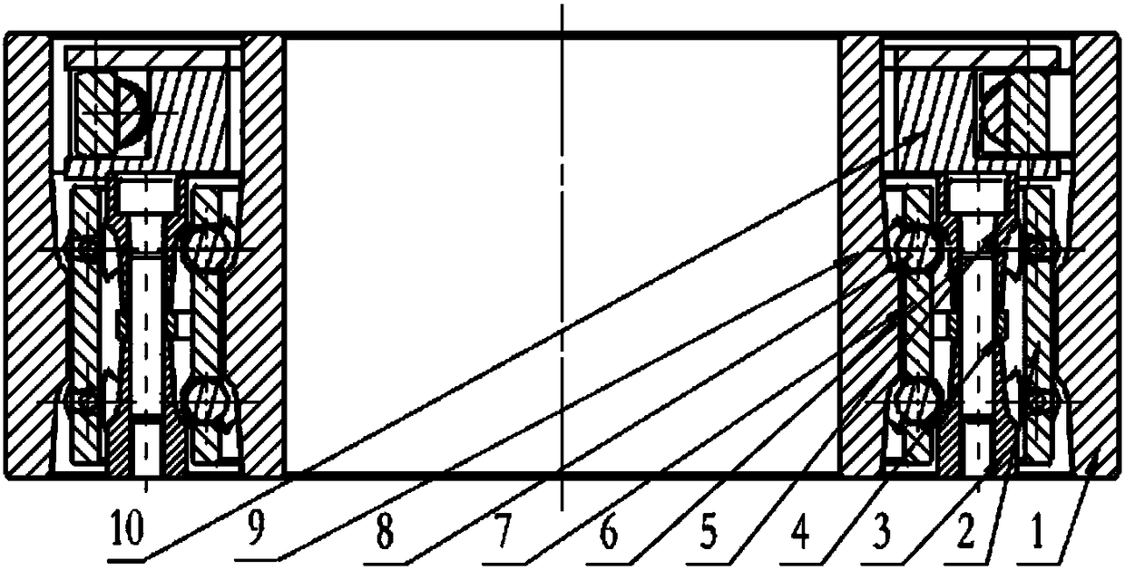
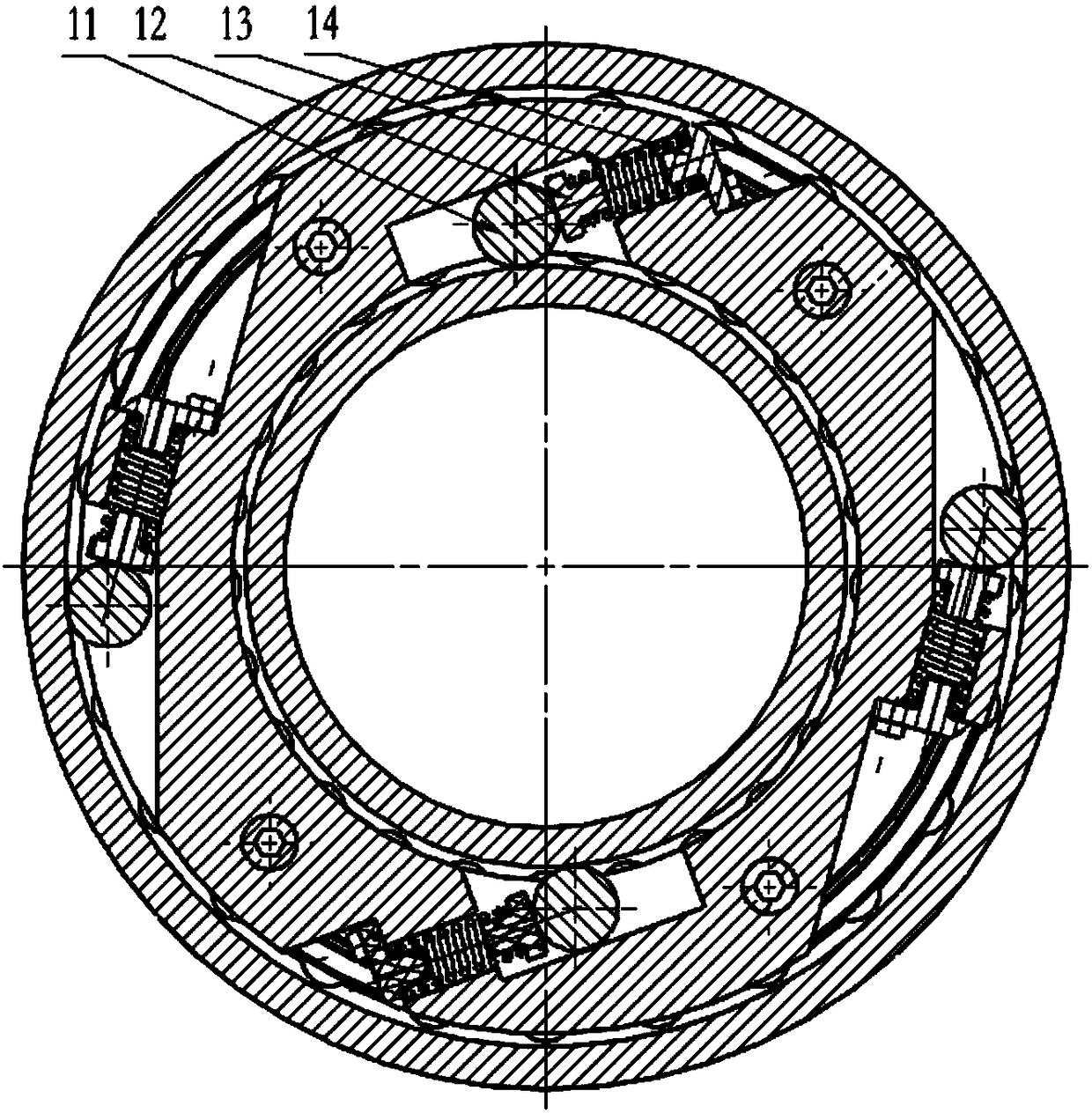
[0011] figure 1 It is the front cross-sectional view of the invented mechanism of swinging friction into rotating friction, figure 2 Its top sectional view. The size of the outer ring 1 is Ф160mm in outer diameter, Ф142mm in inner diameter, 64mm in width, the distance between the two grooves is 22mm, the radius of curvature of the groove is 4.2mm, the material is 9Cr18, and the quenching HRC is ≥ 56; the outer ball cage 2 The outer diameter is Ф141mm, the inner diameter is Ф133mm, and the width is 40mm. The material is polyimide containing molybdenum disulfide. There are 52 holes of Ф8.5mm in double rows, and the distance between the two rows of holes is 22mm. The width is 20mm, the material is 9Cr18, quenching HRC≥56; the outer diameter of the middle pretension ring 4 is Ф128mm, the inner diameter is Ф111mm, the width is 4mm, ...


PUM


Abstract

The invention discloses a mechanism for changing swing friction into rotation friction. The mechanism is composed of an outer ring, a middle ring A, a middle ring B, a middle pre-tightening ring, an inner ring, a ball, an inner ball holder, an outer ball holder, screws, a spring, a spring fixing block, a roller, a roller compaction block and an overrun clutch plate, wherein the middle ring A and the middle ring B are connected with the pre-tightening ring through the screws to form a middle ring; the ball and the ball holder are arranged between the inner ring and the middle ring and between the middle ring and the outer ring; and a bidirectional overrun clutch is connected with the middle ring through the screws. The mechanism disclosed by the invention has the following advantages: local small-angle swing is changed into circumferential rotation, the problems of local wear and wear debris accumulation of a bearing during small-angle swing are solved, the rotation speed uniformity of a precision swing mechanism is improved, and the service life of the swing mechanism is prolonged. The mechanism is of great significance to improving the rotation precision of a spatial solid lubricating high-precision swing mechanism and prolonging the service life.

Description

technical field [0001] The invention relates to a solid lubricating bearing mechanism, in particular to a solid lubricating special rolling bearing mechanism with a two-way overrunning clutch. Background technique [0002] Aerospace optical remote sensing instruments use oscillating mirrors to expand the field of view. Oscillating mirrors are actually the general term for pointing mirrors and swing mechanisms. The structure is that the pointing mirrors are installed on the rotating shaft, and the rotating shaft is supported by bearings. The rotating shaft is driven by a motor to realize the swinging of the pointing mirror. At present, the bearings of the space swing mechanism adopt two lubrication methods: solid lubrication and oil (grease) lubrication, of which oil (grease) lubrication is boundary lubrication. In addition to considering the characteristics of the lubricating oil (grease) itself when using the space, it is also necessary to solve the problem of sealing, Clim...

Claims


Application Information

Patent Timeline
Patent Type & Authority Patents(China)
IPC IPC(8): F16C19/49
CPCF16C19/49
Inventor 胡亭亮王成彬孙胜利孙小进邓容王敏华
Owner SHANGHAI INST OF TECHNICAL PHYSICS - CHINESE ACAD OF SCI
Learn More