
A Dual Plane Probe Deflection Composite Imaging Method

A composite imaging, dual-plane technology, applied in image data processing, 2D image generation, medical science, etc., can solve the problems of increased patient pain, no vertical puncture imaging device, large puncture distance, etc., to reduce complexity. Effect

Active Publication Date: 2019-09-24
SHANTOU INST OF UITRASONIC INSTR CO LTD
View PDF4 Cites 0 Cited by
  • Summary
  • Abstract
  • Description
  • Claims
  • Application Information

AI Technical Summary

Problems solved by technology

[0004] When the puncture needle is punctured in an inclined manner, the puncture distance of the puncture needle is much larger than that of the vertical puncture, which increases the pain of the patient. In addition, due to the oblique puncture, the puncture needle must pass through a large area on the patient's body, which is easy to pierce some blood vessels or other tissue, causing unnecessary damage
[0005] In order to solve the shortcomings of the above-mentioned oblique puncture needles, such as the large puncture distance and easy puncture of some blood vessels or other tissues, the vertical puncture of the puncture needle is the natural first choice. However, there is no better vertical puncture imaging device or technology at present. , among them, the most important problem is that the imaging after deflection is quite complicated to deal with, which is the direction that we have been working on in the field of ultrasound imaging

Method used


Image

  • A Dual Plane Probe Deflection Composite Imaging Method
  • A Dual Plane Probe Deflection Composite Imaging Method
  • A Dual Plane Probe Deflection Composite Imaging Method

Examples


Embodiment Construction

[0029] Further description will be given below in conjunction with the accompanying drawings and preferred embodiments of the present invention.

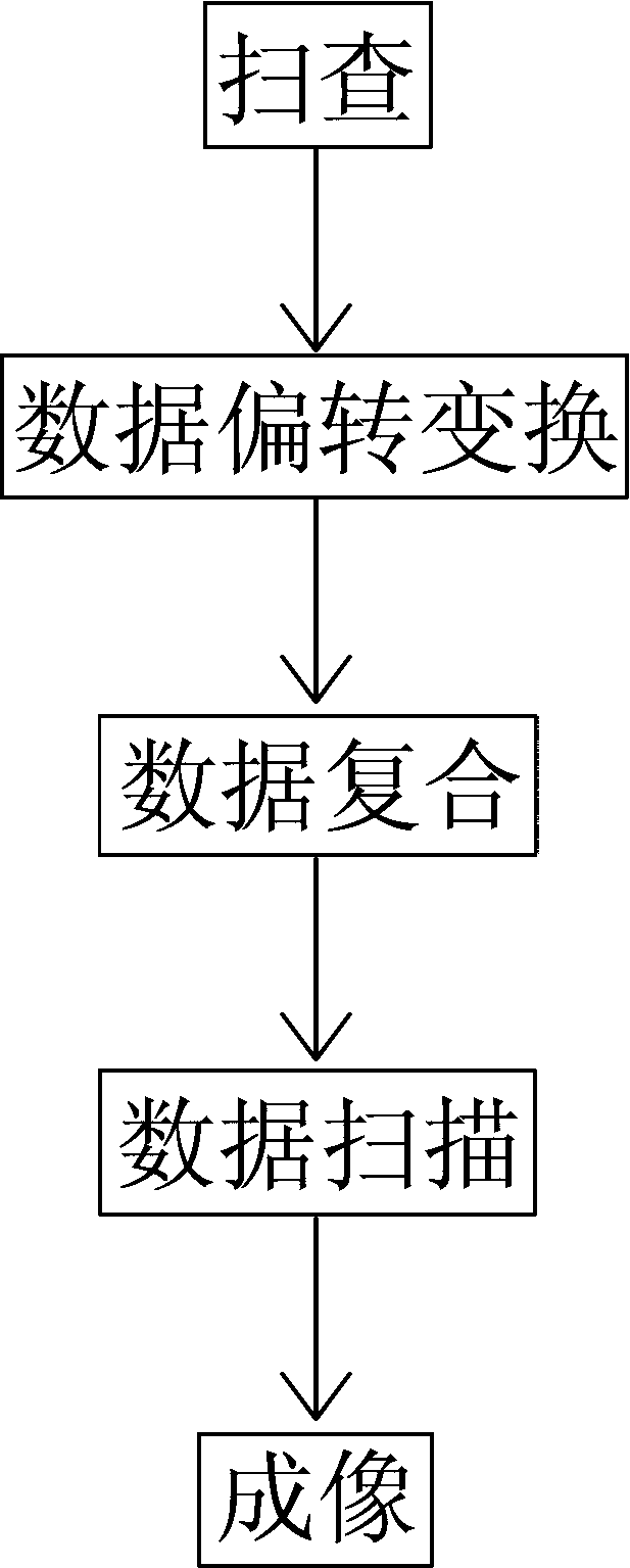
[0030] like figure 1 As shown, this dual-plane probe deflection compound imaging method includes the following steps:

[0031] (1) Use dual-plane probes for scanning: the first-plane ultrasonic probe and the second-plane ultrasonic probe conduct deflection scans respectively, covering the puncture target and the puncture needle;

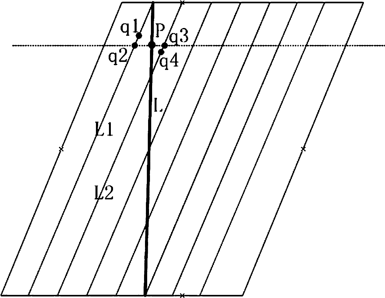
[0032] (2) Data deflection transformation: Transform the original data beams obtained by the first plane ultrasonic probe and the second plane ultrasonic probe into deflected data beams respectively; the first plane ultrasonic probe and the second plane ultrasonic probe convert the original data according to the following steps Transform the harness into a deflection data harness:

[0033] (2-1) Select the original data harness B, which has a deflection angle with the vertical direction;

[0034] (2-2) ...


PUM


Abstract

The invention discloses a double-plane probe deflection compound imaging method, which sequentially comprises the steps of scanning with double plane probes, data deflection conversion, data compounding, data scanning and imaging. In the double-plane probe deflection compound imaging method, before image data is formed by DSC (digital scanning conversion), deflected data harnesses of a first plane ultrasonic probe and a second plane ultrasonic probe are compounded to form a compound data harness, then DSC is performed to form the image data, and imaging is finally performed. In such a manner, simple superimposition processing is only performed for data compounding before the DSC, and the complexity of deflection imaging is greatly reduced, so that puncture is performed in a direction perpendicular to a detected part, the pain of a patient is reduced, unnecessary injury is avoided, and higher safety and reliability are achieved.

Description

technical field [0001] The invention relates to an ultrasonic imaging method, in particular to a dual-plane probe deflection composite imaging method. Background technique [0002] In ultrasound scan imaging, it is necessary to image the puncture target and the puncture needle. [0003] For a single-plane ultrasonic probe, the sound beam is perpendicular to the probe surface, that is, the sound beam is along the vertical direction, while the puncture needle is set on one side of the planar ultrasonic probe. When the puncture needle is punctured perpendicular to the probe surface, the sound The beam cannot cover the puncture target and the puncture needle. Therefore, in order to obtain imaging of the puncture target and the puncture needle, the puncture needle must form an angle with the vertical direction and puncture in an oblique manner. [0004] When the puncture needle is punctured in an inclined manner, the puncture distance of the puncture needle is much larger than t...

Claims


Application Information

Patent Timeline
Patent Type & Authority Patents(China)
IPC IPC(8): A61B17/34A61B90/00G06T11/00
Inventor 李德来陈仲郭境峰余炎雄
Owner SHANTOU INST OF UITRASONIC INSTR CO LTD
Learn More