High sensitivity laser receiver
A laser receiver, high-sensitivity technology, used in instruments, radio wave measurement systems, etc., can solve problems such as limiting laser performance, high noise, and increasing gain, so as to improve system ranging capability, reduce system electrical noise, and improve system. The effect of the signal-to-noise ratio
Inactive Publication Date: 2014-07-09
LUOYANG INST OF ELECTRO OPTICAL EQUIP OF AVIC
View PDF0 Cites 3 Cited by
- Summary
- Abstract
- Description
- Claims
- Application Information
AI Technical Summary
Problems solved by technology
However, due to the harsh airborne working conditions, atmospheric backscatter is likely to interfere with the laser radiator, resulting in backflash, and the noise is large, so it is difficult to effectively increase the gain while suppressing noise, thus limiting the improvement of laser performance
Method used
View moreImage
Smart ImageViewing Examples
Examples
Embodiment Construction
Login to View More PUM
 Abstract
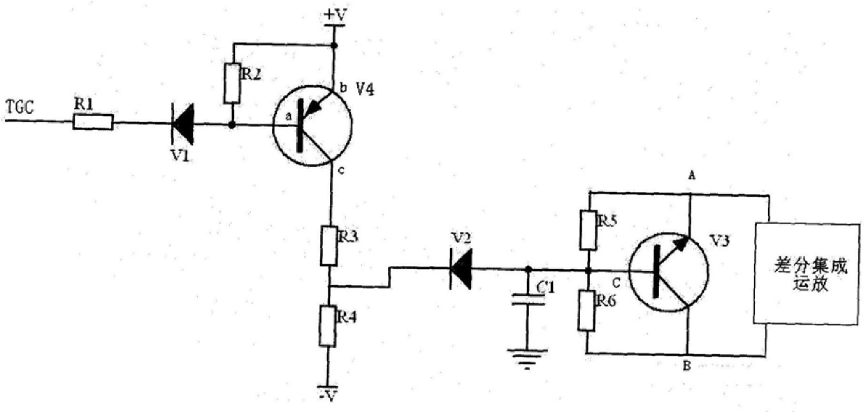
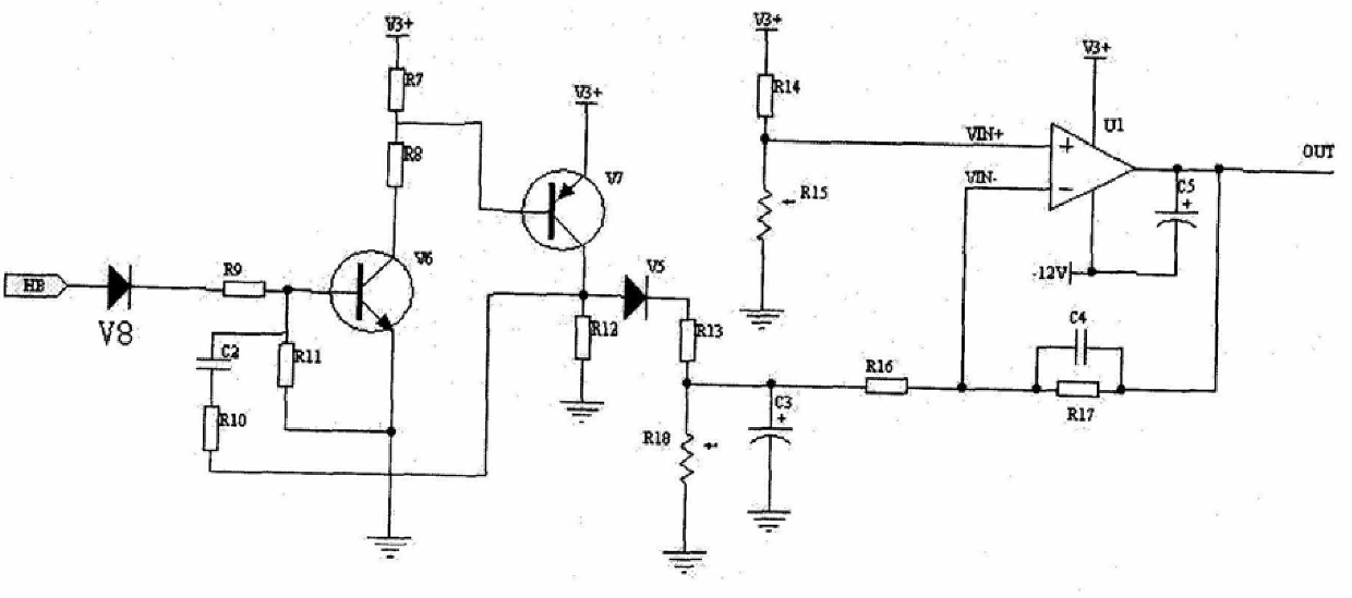
The invention belongs to weak signal amplification and extraction technology, and relates to a high-sensitivity laser receiver. The high-sensitivity laser receiver of the present invention includes a timing control module, a TGC control module, a constant false alarm control module, and an integrated operational amplification module, wherein, the sequential control module passes through the TGC control module, the integrated operational amplification module, and the constant false alarm control module sequentially. The module is then connected to a bias circuit, the other channel of the timing control module is directly connected to the bias circuit, and the integrated operational amplification module is connected to the bias circuit through a photodetector. It adopts the time / temperature gain automatic control technology to effectively avoid the radiation interference of the laser radiator, uses the constant false alarm control technology to make the photodetector work in the best working state, and increases the timing control part of the circuit to make the receiving amplifier circuit When the gain is large, the avalanche bias voltage is removed, so that the laser rangefinder can effectively reduce the electrical noise of the system when it is working, and achieve the goal of reducing voltage, reducing noise, and increasing gain.
Description
High Sensitivity Laser Receiver technical field The invention belongs to weak signal amplification and extraction technology, and relates to a high-sensitivity laser receiver capable of amplifying and extracting weak signals and suppressing system electrical noise. Background technique In the airborne laser rangefinder, in order to meet the miniaturization and modular design requirements of the airborne equipment, and at the same time meet the requirements of improving the effective range of laser ranging products, the laser receiving circuit needs a small modular design. However, due to the harsh airborne working conditions, atmospheric backscatter is likely to interfere with the laser radiator, resulting in backflash, and the noise is large. It is difficult to effectively increase the gain while suppressing noise, thus limiting the improvement of laser performance. Contents of the invention The purpose of the present invention is to provide a laser receiver which can...
Claims
Login to View More Application Information
Patent Timeline
 IPC IPC(8): G01S7/486
Inventor 樊宪唐
Owner LUOYANG INST OF ELECTRO OPTICAL EQUIP OF AVIC
Features
- R&D
- Intellectual Property
- Life Sciences
- Materials
- Tech Scout
- Unparalleled Data Quality
- Higher Quality Content
- 60% Fewer Hallucinations
Learn More Browse by: Latest US Patents, China's latest patents, Technical Efficacy Thesaurus, Application Domain, Technology Topic, Popular Technical Reports.
© 2025 PatSnap. All rights reserved.Legal|Privacy policy|Modern Slavery Act Transparency Statement|Sitemap|About US| Contact US: help@patsnap.com


