Printed multi-band antenna

A multi-frequency antenna and printing technology, applied in antennas, resonant antennas, antenna grounding devices, etc., can solve the problems of high cost, complex antenna structure, and lack of flexibility in use, and achieve low cost, diverse applications, and easy adjustments Effect

Inactive Publication Date: 2017-01-18
ARCADYAN
View PDF3 Cites 0 Cited by
  • Summary
  • Abstract
  • Description
  • Claims
  • Application Information

AI Technical Summary

Problems solved by technology

[0005] In view of the above-mentioned problems in the prior art, one of the purposes of the present invention is to provide a printed multi-frequency antenna to solve the existing problems of complex structure, high cost, and lack of flexibility in use

Method used


Image

  • Printed multi-band antenna
  • Printed multi-band antenna
  • Printed multi-band antenna

Examples


Embodiment Construction

[0039] Embodiments of the printed multi-frequency antenna provided according to the present invention will be described below with reference to the related drawings.

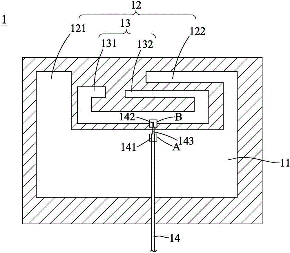
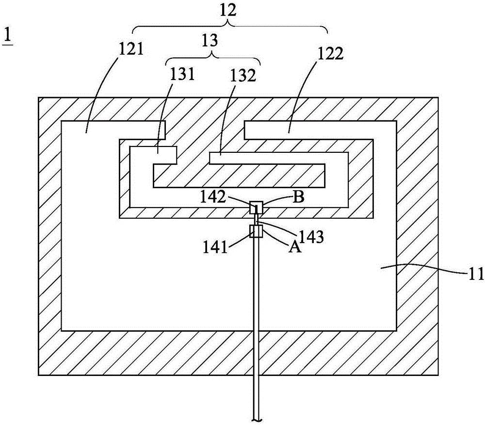
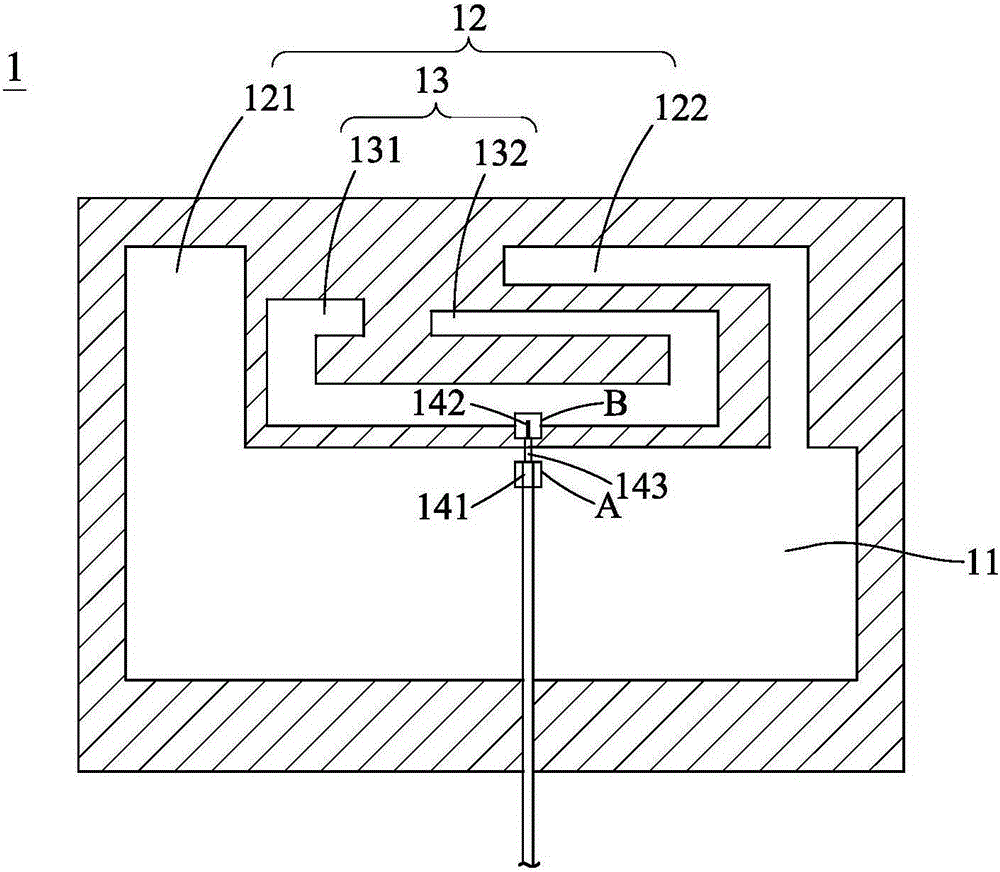
[0040] like figure 1 Shown is a schematic diagram of the first embodiment of the printed multi-frequency antenna provided by the present invention. As shown in the figure, the printed multi-frequency antenna 1 is used in a small-area independent circuit board, which may include a grounding area 11 , a first radiator 12 and a second radiator 13 .

[0041] The grounding area 11 can be connected to the ground plane 141 in the RF cable 14, and the RF cable 141 can be connected to the RF signal module (not shown in the figure). The first radiator 12 can be connected to the grounding area 11 and form a space area with the inner side of the grounding area 11. The first radiator 12 can include a first left branch 121 and a first right branch 122. The first left branch 121 The first right branch 122 may be located on o...


PUM


Abstract

A printed multi-band antenna is provided, which may include a grounding area, a first radiating body and a second radiating body. The grounding area may connect to the grounding layer of a RF cable connecting to a RF signal module. The first radiating body may connect to the grounding area and include a first left branch and a first right branch. The first left branch may be at one side of the joint of the RF cable and the grounding area; the first right branch may be at the opposite side. The first radiating body and the internal side edge of the grounding area constitute one space area. The second radiating body may be arranged inside the space area. The second radiating body may connect to the signal wire of the RF cable, and include a second left branch and a second right branch. The second left branch may be at one side of the joint of the RF cable, and the second radiating body and the second right branch may be at the opposite side.

Description

technical field [0001] The present invention relates to a multi-frequency antenna, in particular to a monopole-type and coupling-type printed antenna. Background technique [0002] Nowadays, because mobile devices have become indispensable items in people's lives, it has also led to the vigorous development of the communication industry. Because of this, all kinds of small antennas have been developed and widely used in various For example, a Planarinverse-F antenna or a Monopole antenna. However, the above-mentioned existing antennas suffer from a number of nasty shortcomings. [0003] For example, the structure of the planar inverted-F antenna is relatively complex, and since the planar inverted-F antenna is a three-dimensional antenna, it requires additional mold cost and assembly cost. The manufacturing cost of products using this antenna reduces its commercial competitiveness; in addition, the flat inverted-F antenna has a narrow bandwidth, and the flat inverted-F ant...

Claims


Application Information

Patent Timeline
Patent Type & Authority Applications(China)
IPC IPC(8): H01Q1/38H01Q1/50H01Q1/36
CPCH01Q1/48H01Q9/42H01Q5/378H01Q1/38H01Q9/04
Inventor 黄智勇罗国彰
Owner ARCADYAN
Why Eureka
Try Eureka