


Quick Research
Generate reliable direction feasibility study reports for your R&D in just a few steps.

Technical Q&A
Discover and master advanced knowledge NOW. Basics, ideas, possibilities, all at once.

Find Solutions
As an expert in R&D theories, this can generate solutions to your technical problems instantly.

Evaluate Feasibility
Analyze your overall solution with one click, know your potential R&D risks in advance.

Monitor Landscape
Get weekly tech updates, stay abreast of the latest tech innovations and key insights.
Constant Torque Control Method for Horizontal Screw Decanter
A technology of a decanter centrifuge and a control method, which can be applied in directions such as centrifuges, can solve problems such as the deterioration of clear liquid turbidity, and achieve the effect of ensuring that it does not exceed the standard.
- Summary
- Abstract
- Description
- Claims
- Application Information
AI Technical Summary
Problems solved by technology
Method used
Image


Examples
Embodiment Construction
[0018] Below in conjunction with embodiment, the present invention is described in detail
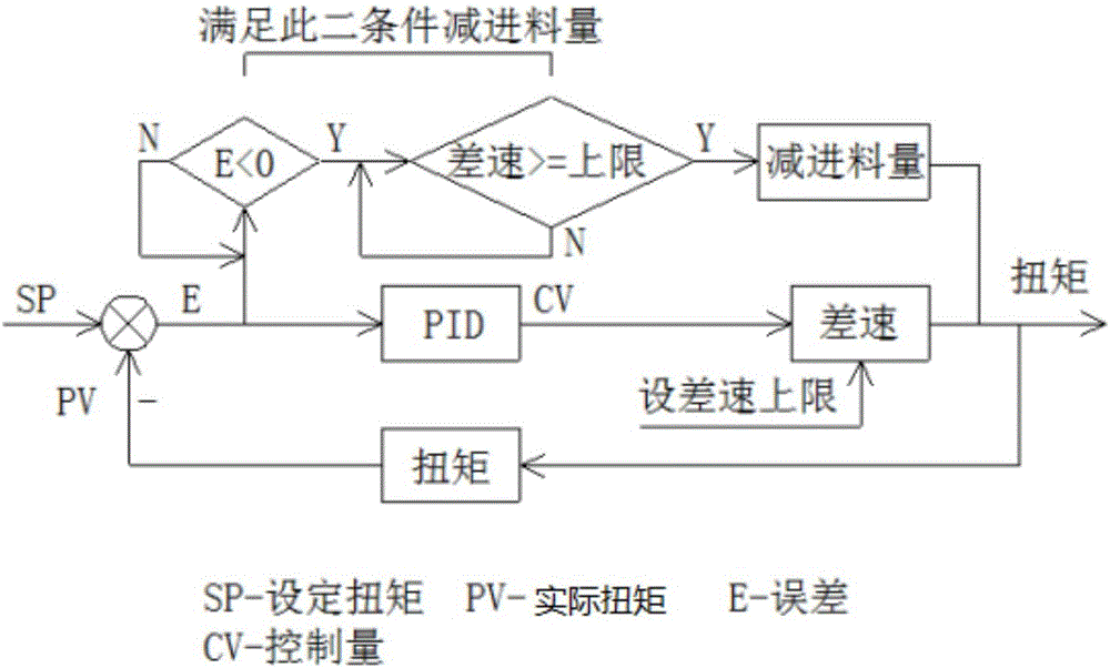
[0019] as attached figure 2 As shown, a constant torque control method of a decanter centrifuge is characterized in that it comprises the following steps:
[0020] In the first step, the centrifuge is rotated at high speed,
[0021] The second step is to feed the material to the centrifuge. Under the action of centrifugal force, the material begins to separate from solid to liquid, and the torque begins to rise;
[0022] In the third step, as long as the differential speed is detected the set torque value, the PID adjustment will cause the differential speed to rise. The increase in the differential speed will shorten the time that the material stays in the centrifuge and the separation effect will decrease. The torque falls back to the set torque value;
[0023] If the actual detected torque is less than the set torque value, the PID adjustment will cause the differential speed to...
PUM
 Abstract
Description
Claims
Application Information
 - R&D Engineer
- R&D Manager
- IP Professional
- Industry Leading Data Capabilities
- Powerful AI technology
- Patent DNA Extraction
Browse by: Latest US Patents, China's latest patents, Technical Efficacy Thesaurus, Application Domain, Technology Topic, Popular Technical Reports.
© 2024 PatSnap. All rights reserved.Legal|Privacy policy|Modern Slavery Act Transparency Statement|Sitemap|About US| Contact US: help@patsnap.com