
Electrical wire pipe threading and wire-leading apparatus and threading and wire-leading method thereof

A technology for threading lead wires and electric wires, which is applied to the installation of cable installation devices, electrical components, and cables, etc., which can solve the problems of long time-consuming threading work, and achieve the effects of high construction efficiency, wide application range, and reduced consumption

Active Publication Date: 2017-01-11
CHINA FIRST METALLURGICAL GROUP
View PDF6 Cites 3 Cited by
  • Summary
  • Abstract
  • Description
  • Claims
  • Application Information

AI Technical Summary

Problems solved by technology

[0004] The technical problem to be solved by the present invention is to provide an electrical conduit threading device and a threading method for the above-mentioned deficiencies in the existing electric conduit threading, which solves the problem of long time-consuming and low efficiency of threading work in concealed electric conduits problems, reduce construction costs and improve work efficiency

Method used


Image

  • Electrical wire pipe threading and wire-leading apparatus and threading and wire-leading method thereof
  • Electrical wire pipe threading and wire-leading apparatus and threading and wire-leading method thereof
  • Electrical wire pipe threading and wire-leading apparatus and threading and wire-leading method thereof

Examples


Embodiment Construction

[0031] The present invention will be further described below in conjunction with the accompanying drawings and specific implementation.

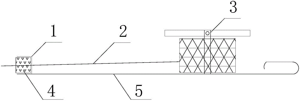
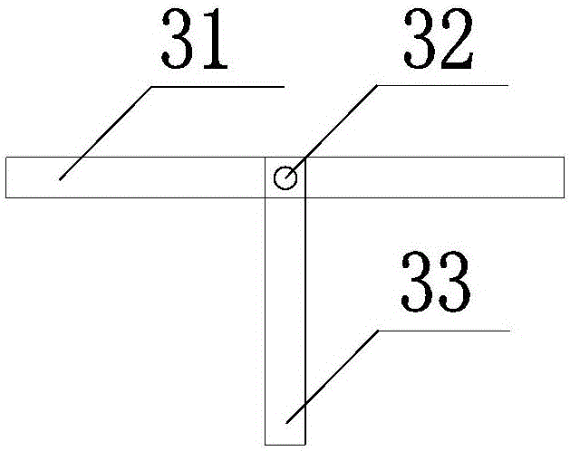
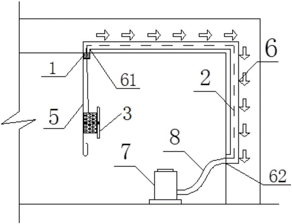
[0032] figure 1 The structural schematic diagram of the electric wire tube threading device provided by the present invention, combined with figure 1 As shown, the electrical conduit threading device includes a rod member 5, a groove member 1, a rubber sheet 4, a T-shaped bracket 3, a ribbon wire 2 and a vacuum cleaner 7, one end of the groove member 1 is open, the other end and the side are closed, and One end of the closed end has a hole in the middle, one end of the rod member 5 is welded to the side of the groove member 1, the rubber sheet 4 is arranged in the groove member 1, and the middle of the rubber sheet 4 has an opening at the same position as the hole of the groove member 4; T-shaped support 3 comprises cross bar 31 and vertical bar 33, and cross bar 31 is connected with vertical bar 33 with screw 32, and the vertical bar 31 of...


PUM


Abstract

Provided is an electrical wire pipe threading and wire-leading apparatus. The apparatus comprises a rod member, a groove member, a rubber sheet, a T-shaped support, a tape wire, and a dust collector, one end of the groove member is open, the other end and side surfaces of the groove member are closed, the middle position of the closed end is provided with an open hole, one end of the rod member is welded at the side surface of the groove member, a vertical rod of the T-shaped support is sleeved by the tape wire, and a rope head of the tape wire penetrates through the open hole at the closed end of the groove member and an opening of the rubber sheet. A threading and wire-leading method of the electrical wire pipe threading and wire-leading apparatus includes: forming a closed space in an electrical wire pipe through the rubber sheet at an inlet end of the electrical wire pipe and an air suction hose at an outlet end; sucking the tape wire at the inlet end of the electrical wire pipe into the outlet end of the electrical wire pipe by employing the suction of the dust collector, wherein the air suction hose of the dust collector is arranged at the outlet end of the electrical wire pipe; and accomplishing the threading operation in the electrical wire pipe through pulling of the tape wire at the outlet end of the electrical wire pipe. According to the apparatus and the method, problems of long time consumption and low efficiency of the threading operation in concealed laying of the electrical wire pipe are solved, the construction cost is reduced, the work efficiency is improved, and the apparatus and the method are applicable to various construction environments.

Description

technical field [0001] The invention belongs to the construction field of construction electrical engineering cables and electric wires fast-piercing pipes, and in particular relates to an electric wire pipe threading device and a threading method thereof. Background technique [0002] In the construction of modern construction projects, electrical conduits are generally pre-embedded in walls and floors in the form of concealed laying. After the main structure is constructed, the electrical conduit threading operation begins. The usual methods are as follows: when the electrical pipeline is pre-embedded, place the thin iron wire in the electrical conduit in advance; out. The above-mentioned pre-embedded electrical conduit threading method has the following defects: the construction period of the main structure is long, the iron wire in the electric conduit will be corroded if placed for a long time, and it is easy to break during the threading process, and the iron wire bel...

Claims


Application Information

Patent Timeline
Patent Type & Authority Applications(China)
IPC IPC(8): H02G1/08
CPCH02G1/083H02G1/086
Inventor 孙羽佳姜富瑜郭继舟李少祥
Owner CHINA FIRST METALLURGICAL GROUP
Learn More