
Display panel and testing method thereof

A technology of display panel and test method, applied in the direction of static indicator, instrument, etc., can solve the problem of not being able to test the signal line completely

Inactive Publication Date: 2017-01-11
WUHAN CHINA STAR OPTOELECTRONICS TECH CO LTD
View PDF7 Cites 7 Cited by
  • Summary
  • Abstract
  • Description
  • Claims
  • Application Information

AI Technical Summary

Problems solved by technology

[0006] The present invention provides a display panel and a testing method thereof to solve the problem that signal lines (such as scanning lines, data lines, etc.) in the display panel cannot be completely tested in the prior art

Method used


Image

  • Display panel and testing method thereof
  • Display panel and testing method thereof
  • Display panel and testing method thereof

Examples


Embodiment Construction

[0022] The technical solutions in the embodiments of the present invention will be clearly and completely described below in conjunction with the accompanying drawings in the embodiments of the present invention. Obviously, the described embodiments are only a part of the embodiments of the present invention, rather than all the embodiments. Based on the embodiments of the present invention, all other embodiments obtained by those of ordinary skill in the art without creative work shall fall within the protection scope of the present invention.

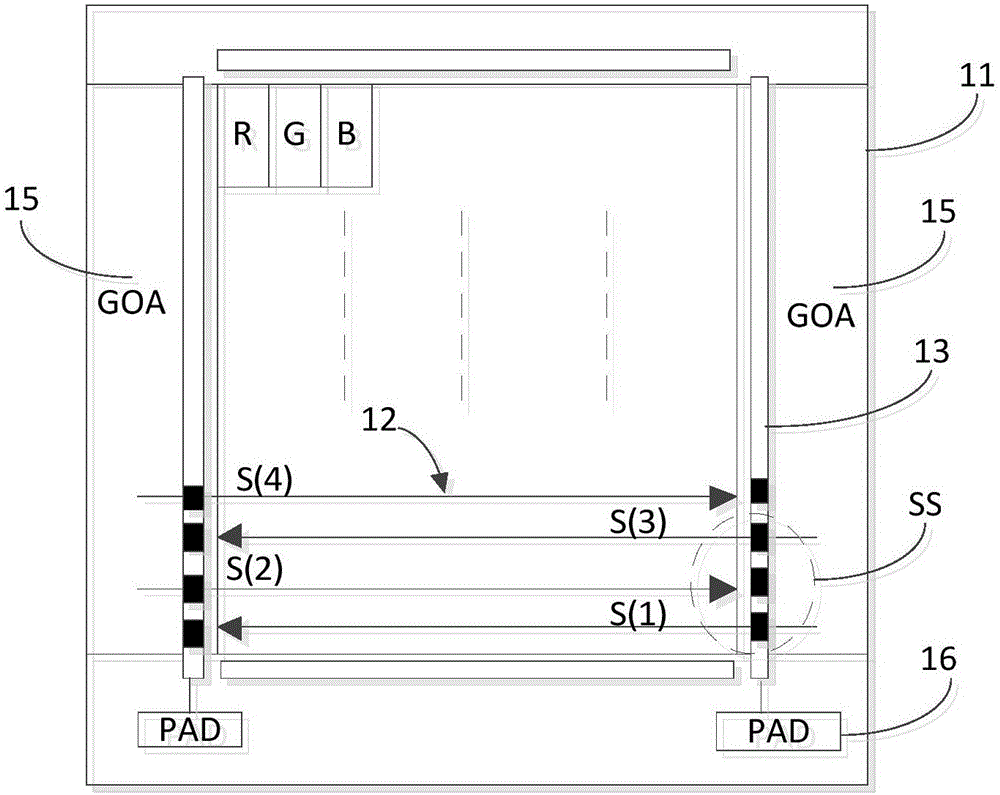
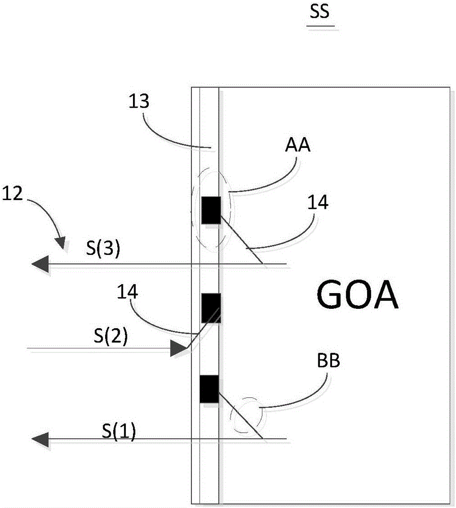
[0023] figure 2 Is a schematic diagram of the structure of the display panel of the embodiment of the present invention, image 3 Yes figure 2 Shown is an enlarged schematic view of the SS area in the display panel. Such as figure 2 with image 3 As shown, the display panel includes a substrate 11, a circuit under test 12 disposed on the substrate 11, a first lead line 13 and a second lead line 14, and a circuit device 15 connected to ...


PUM


Abstract

The invention discloses a display panel and a testing method thereof. The display panel comprises a first lead circuit and a second lead circuit, the second lead circuit is electrically connected with one in a circuit to be tested and the first lead circuit, and the second lead circuit and the other one of the circuit to be tested and the first lead circuit are arranged in an insulating manner at intervals. The testing method includes the steps: electrically connecting the second lead circuit with the other one of the circuit to be tested and the first lead circuit, and enabling the first lead circuit to be electrically connected with the circuit to be tested; testing the circuit to be tested or a circuit device connected with the circuit to be tested by the first lead circuit; disconnecting the second lead circuit and further disconnecting electrical connection between the circuit to be tested and the first lead circuit after testing is finished. By the aid of the mode, all signal wires in the display panel can be accurately and completely tested, and real and effective data are provided for design verification of the display panel.

Description

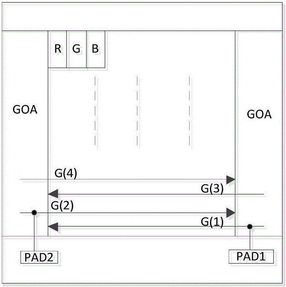
Technical field [0001] The present invention relates to the field of liquid crystal display, in particular to a display panel and a test method thereof. Background technique [0002] At present, most small-size liquid crystal displays adopt GOA design. Among them, GOA design refers to the use of the existing Array process in thin film transistor liquid crystal displays to fabricate the gate drive (Gate) signal on the Array substrate to achieve a scan of the liquid crystal display. technology. However, since the GOA circuit is built into the display panel, it is impossible to actually measure the gate drive signal output by the scan line in the GOA circuit like an external circuit. [0003] In order to solve the above problems, the prior art approach is to lead at least one test pad in the non-display area of ​​the display panel and close to the output terminal of the GOA circuit, and bridge the scan line close to the non-display area to the test pad for testing. For example, such...

Claims


Application Information

Patent Timeline
IPC IPC(8): G09G3/00
CPCG09G3/006
Inventor 文松贤
Owner WUHAN CHINA STAR OPTOELECTRONICS TECH CO LTD
Learn More