Holographic display device

A technology for holographic display and position information, which is applied in holographic process, digital holographic electronic components, characteristics of hologram objects, etc.

Inactive Publication Date: 2017-01-11
BOE TECH GRP CO LTD
View PDF9 Cites 3 Cited by
  • Summary
  • Abstract
  • Description
  • Claims
  • Application Information

AI Technical Summary

Problems solved by technology

However, the current digital holographic display device can only display one holographic image, which is not conducive to multiple people viewing it at the same time.

Method used


Image

  • Holographic display device
  • Holographic display device
  • Holographic display device

Examples


Embodiment approach

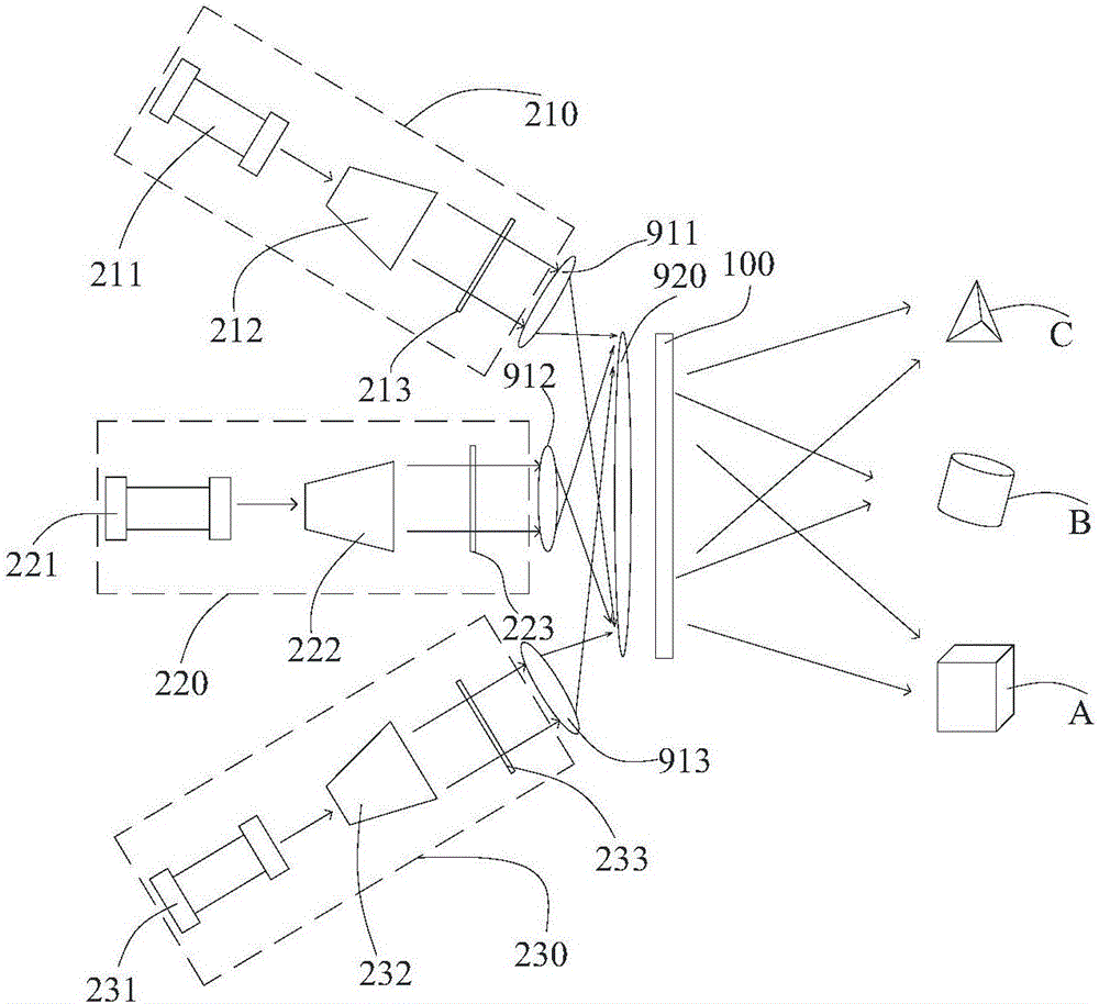
[0056] As a preferred implementation manner of the present invention, the number of the backlight sources is three. Therefore, the frequency at which each backlight illuminates the spatial light modulator 100 is 40 Hz.

[0057] In the present invention, there is no special limitation on the specific structure of the backlight source. For example, each of the backlight sources includes a light emitting component capable of emitting coherent light parallel to the spatial light modulator, and the lens component includes a plurality of first lens (in figure 1 Among them are the first lens 911, the first lens 912 and the first lens 913) and the second lens 920 arranged between the first lens and the spatial light modulator 100, the first lens can transmit the corresponding backlight The parallel plane coherent light is guided to a predetermined position of the second lens 920 , and the second lens 920 can respectively guide the light emitted by each first lens to the spatial ligh...


PUM


Abstract

The invention provides a holographic display device which comprises a spatial light modulator and further comprises a lens component and multiple backlight sources. The multiple backlight sources are arranged on the light-in side of the spatial light modulator. The lens component is arranged between the backlight sources and the spatial light modulator. The multiple backlight sources can emit light in different directions to the lens component. The lens component can guide the received light in different directions to the spatial light modulator so images are formed in different positions on the light-out side of the spatial light modulator. The holographic display device can display multiple stereo images in different positions.

Description

technical field [0001] The present invention relates to the field of display, in particular to a holographic display device. Background technique [0002] Holographic technology is a recording and reproduction technology that uses the principles of interference and diffraction to record and reproduce the real three-dimensional image of an object. The first step of holographic technology is to use the interference principle to record the light wave information of the object. The object to be photographed forms a diffuse reflection object beam under laser irradiation, and the other part of the laser beam is irradiated on the holographic film as a reference beam, and interferes with the object beam. , to convert the phase and amplitude of each point on the object light wave into a spatially varying intensity, so as to use the contrast and interval between the interference fringes to record all the object light waves; the second step is to use the principle of diffraction to rep...

Claims


Application Information

Patent Timeline
Patent Type & Authority Applications(China)
IPC IPC(8): G03H1/22
CPCG03H1/2205G03H2001/221G06F3/013G02B30/34G03H1/10G03H2001/0212G03H2210/30G03H2210/56G03H2226/05G06F3/012G06F2203/04802
Inventor 李盼
Owner BOE TECH GRP CO LTD
Why Eureka
Try Eureka