
Optical imaging camera

An optical imaging lens and imaging technology, applied in the field of optical lenses, can solve the problems of increasing the length of the lens, involving material properties, etc., and achieve the effect of ensuring the imaging quality, reducing the length of the lens, and enhancing the clarity

Active Publication Date: 2017-01-11
GENIUS ELECTRONICS OPTICAL XIAMEN
View PDF7 Cites 18 Cited by
  • Summary
  • Abstract
  • Description
  • Claims
  • Application Information

AI Technical Summary

Problems solved by technology

[0003] However, optical lens design does not simply reduce the proportion of a lens with good imaging quality to produce an optical lens with both image quality and miniaturization. The design process not only involves material characteristics, but also production and assembly yields. practical problems
However, using a voice coil motor to adjust the position of the imaging plane to achieve autofocus results in an increase in the length of the lens during the operation of the voice coil motor

Method used


Image

  • Optical imaging camera
  • Optical imaging camera
  • Optical imaging camera

Examples


Embodiment Construction

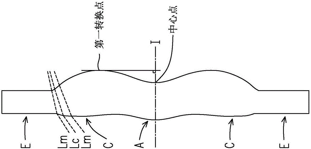
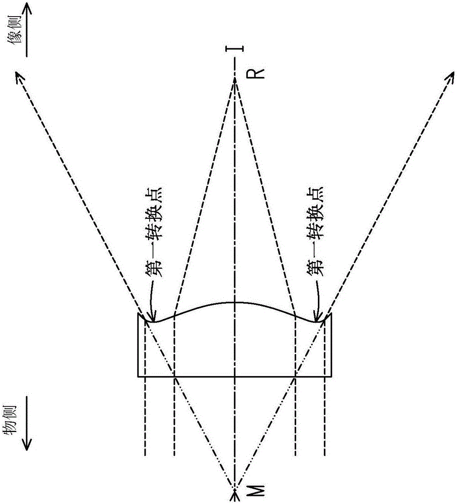
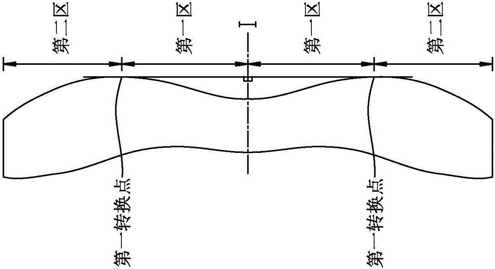
[0059] The term "a lens has a positive refractive power (or negative refractive power)" in this specification refers to the positive (or negative) refractive power of the lens on the optical axis calculated by Gaussian optics theory. The image side and object side are defined as the range through which the imaging light passes, where the imaging light includes the chief ray Lc and the marginal ray Lm, such as figure 1 As shown, I is the optical axis and this lens is radially symmetrical to each other with the optical axis I as the symmetry axis. The area where the light rays pass through the optical axis is the area A near the optical axis, and the area where the marginal light rays pass is the area C near the circumference. , In addition, the lens also includes an extension E (that is, the area near the circumference C radially outward), which is used for the lens to be assembled in an optical imaging lens, and the ideal imaging light does not pass through the extension E , b...


PUM


Abstract

The invention discloses an optical imaging camera which comprises multiple lenses in sequence along an optical axis between an object side and an image side, wherein each lens has an object-side surface and an image-side surface. The lenses are provided with at least one variable gap, and the lens closest to the object side has positive refractive rate. The optical imaging camera satisfies Delta G / Gv<=0.1, wherein Delta G is the absolute value of the difference between a first value and a second value of the length of the variable gap on the optical axis when the camera is focused to objects which are infinitely far and 500mm far respectively, and Gv is the second value. The optical imaging camera of the invention is used for optical photography imaging. The lens length of the optical imaging camera is shortened effectively, the imaging quality is ensured, and the imaging resolution of distant or close photographing is strengthened. In addition, the design and processing difficulty of the optical imaging camera is low.

Description

technical field [0001] The present invention relates to an optical lens, and in particular to an optical imaging lens. Background technique [0002] The specifications of consumer electronic products are changing with each passing day (such as mobile phones, cameras, tablet computers, personal digital assistants, car photography devices, etc.), and the pace of pursuit of lightness and compactness has never slowed down. Therefore, the key components of electronic products such as optical lenses It must also be continuously improved to meet the needs of consumers. The most important characteristics of optical lenses are nothing more than image quality and volume. Among them, in terms of imaging quality, with the advancement of image sensing technology, consumers' requirements for imaging quality will also increase. Therefore, in the field of optical lens design, in addition to pursuing thinner lenses, lens imaging must also be considered. quality and performance. In order t...

Claims


Application Information

Patent Timeline
Patent Type & Authority Applications(China)
IPC IPC(8): G02B13/00G02B13/18
CPCG02B13/002G02B13/18G02B9/60G02B9/62G02B13/004G02B13/0045G02B9/34G02B27/0025
Inventor 张国文陈白娜
Owner GENIUS ELECTRONICS OPTICAL XIAMEN
Learn More