Heating system by utilizing shallow layer geothermal energy in severe cold area

A technology of heating system and geothermal energy, which is applied in the direction of heating system, household heating, application, etc., can solve the problems of poor performance ratio, high input and operation costs, surface environmental pollution, etc., and achieve novel structure, high performance ratio, The effect of broadening the geographical scope

Inactive Publication Date: 2017-01-11
王作韬
View PDF5 Cites 1 Cited by
  • Summary
  • Abstract
  • Description
  • Claims
  • Application Information

AI Technical Summary

Problems solved by technology

However, these methods have certain limitations in severe cold regions.
1. The air source heat pump works in the temperature environment below minus 20 degrees, and the performance ratio (cop) is poor, so it is not suitable for severe cold areas; 2. The water source heat pump needs a hot water source, but it is difficult to explore the underground hot water source, and Exploiting underground hot water for heating is easy to destroy groundwater resources, and it is also difficult to recharge, which is likely to cause pollution to the surface environment; there are very few hot water sources that can extract heat energy and reuse it on the ground, so the heat energy that can be extracted is extremely limited; 3. Use water as The soil source heat pump of the medium requires a higher temperature of the underground soil, but the temperature in the shallow area within 300 meters underground in the severe cold area is low, and the performance of heat energy heating is relatively poor when using water as the medium to extract heat energy, while the extraction of deep geothermal energy requires an early investment. and higher running costs
Based on the above reasons, the development and utilization of clean energy in winter in my country's severe cold regions has not been developed.

Method used


Image

  • Heating system by utilizing shallow layer geothermal energy in severe cold area

Examples


Embodiment Construction

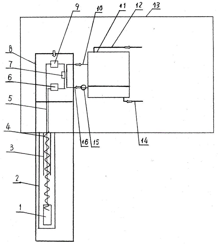
[0010] Embodiments of the present invention will be described in detail below in conjunction with the accompanying drawings. A heating system using shallow geothermal energy in severe cold areas, setting up a pump room 13 on the ground, installing a compressor 9 of a heat pump unit 8 in the pump room 13, an air cooler 7, an expansion valve 6 and a cold water chamber and A water tank 11 composed of a hot water chamber is equipped with a cold water return pipe 16 communicated with the cold water chamber and a heat exchange water pipe 10 communicated with the hot water chamber on the water tank 11. The water pump 15 is installed on the cold water return pipe 16. The cold water The return pipe 16 and the heat exchange water pipe 10 are connected with the heat pump unit 8, and the hot water output pipe 12 and the cold water input pipe 14 are respectively connected with the hot water chamber and the cold water chamber of the water tank 11; A geothermal well 2 is set up inside, and t...


PUM


Abstract

The invention discloses a heating system by utilizing shallow layer geothermal energy in a severe cold area and belongs to the clean energy utilization technology. A geothermal well is opened in a shallow layer with the depth of 150-200m underground in the severe cold area; an evaporator and an insulation bushing are installed in the geothermal well; a CO2 input pipe and a CO2 output pipe are assembled in the insulation bushing; the CO2 input pipe is wholly in a spiral body shape; the CO2 output pipe is arranged in the spiral body of the CO2 input pipe; the two ends of the CO2 input pipe communicate with the evaporator and an expansion valve respectively; and the two ends of the CO2 output pipe communicate with the evaporator and a compressor respectively. By changing the structural form of a traditional carbon dioxide heat pump unit, the heating system can still normally and efficiently run under the environment of the severe cold area with poor air temperature condition and has the characteristics of reasonable and simple structure, high price-performance ratio and supplying support for developing and applying the geothermal energy in the severe cold area.

Description

technical field [0001] The invention belongs to clean energy utilization technology, and mainly relates to a shallow geothermal energy utilization system. Background technique [0002] At present, there are three main ways to develop and utilize clean energy for heating. One is air source heat pump, which extracts heat energy from the air for heating; the other is water source heat pump, which extracts heat energy from hot water for heating; the other is soil source heat pump. Heat pumps use water as a medium to extract thermal energy from underground soil for heating. However, these methods have certain limitations in severe cold regions. 1. The air source heat pump works in the temperature environment below minus 20 degrees, and the performance ratio (cop) is poor, so it is not suitable for severe cold areas; 2. The water source heat pump needs a hot water source, but it is difficult to explore the underground hot water source, and Exploiting underground hot water for he...

Claims


Application Information

Patent Timeline
IPC IPC(8): F25B30/06F25B30/02F24D15/04
CPCF24D15/04F25B30/02F25B30/06
Inventor 王作韬
Owner 王作韬
Why Eureka
Try Eureka