Machine body water cavity arrangement form

A water cavity and body technology, applied in mechanical equipment, engine components, machines/engines, etc., can solve the problems of cantilevered sand core, poor uniformity, dead water area in the water chamber, etc., to avoid dead water area and uniform water flow. Sexual satisfaction, uniform cooling effect

Active Publication Date: 2017-01-11
WEICHAI POWER CO LTD
View PDF6 Cites 0 Cited by
  • Summary
  • Abstract
  • Description
  • Claims
  • Application Information

AI Technical Summary

Problems solved by technology

[0005] The purpose of the present invention is to solve the problems of poor uniformity of water flow in each cylinder of the existing engine water distribution cavity, dead water area in the water distribution cavity, and cantilever defects in the sand core

Method used


Image

  • Machine body water cavity arrangement form
  • Machine body water cavity arrangement form
  • Machine body water cavity arrangement form

Examples


Embodiment Construction

[0015] Exemplary embodiments of the present disclosure will be described in more detail below with reference to the accompanying drawings. Although exemplary embodiments of the present disclosure are shown in the drawings, it should be understood that the present disclosure may be embodied in various forms and should not be limited by the embodiments set forth herein. Rather, these embodiments are provided for more thorough understanding of the present disclosure and to fully convey the scope of the present disclosure to those skilled in the art.

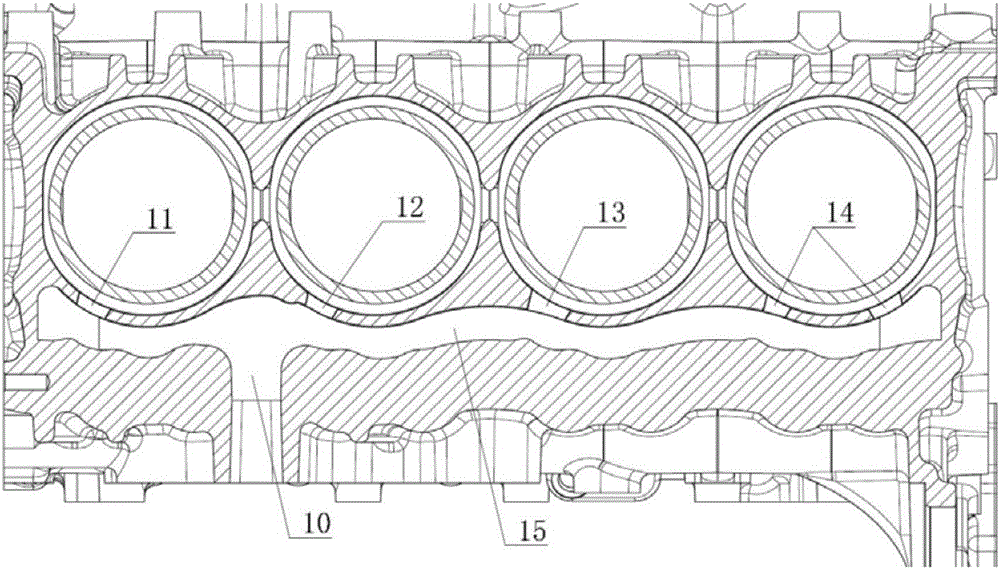
[0016] According to the embodiment of the present invention, an arrangement form of the water cavity of the body is proposed, and the cooling system includes a main water inlet 10 , first to fourth water inlets 11 - 14 and a communication pipe 15 . The water flows in from the main water inlet hole, and enters the first to fourth water inlet holes respectively through the flow pipe. Different from the prior art, the water inlet hole...


PUM


Abstract

The invention provides a machine body water cavity arrangement form. A main water inlet hole and a plurality of branched water inlet holes are included. The number of the water inlet holes is greater than that of air cylinders. The main water inlet hole communicates with the branched water inlet holes through fluid. The machine body water cavity arrangement form is characterized in that the cross sections of the water inlet holes are not completely identical. Through the arrangement, the uniformity of water flowing into all the air cylinders is guaranteed, all the air cylinders are also cooled uniformly correspondingly, existence of dead water zones is avoided, and suspension of cores is avoided, and the strength of sand cores can be enhanced.

Description

technical field [0001] The invention relates to an engine cooling system, in particular to an engine water distribution chamber. Background technique [0002] In the structure of diesel engine body, due to the limitation of the structure and the requirements of the layout of the whole machine, the existence and arrangement of the water jacket and water chamber are not the same. In general, if the space permits, before the water jacket, design a section of water distribution chamber, which can stabilize the pressure and allow the cooling water to enter each cylinder separately. The arrangement of the water distribution cavity in the prior art is generally one water inlet hole per cylinder, such as figure 1 shown. [0003] For this scheme of one water inlet hole per cylinder, since most of the existing cylinder heads are integral cylinder heads, taking a four-cylinder machine as an example, one water inlet hole for four cylinders is generally at the front end of the cylinder...

Claims


Application Information

Patent Timeline
IPC IPC(8): F02F1/10
CPCF02F1/10
Inventor 朱海燕胡琦山吴雪雷王超
Owner WEICHAI POWER CO LTD
Why Eureka
Try Eureka