
A kind of anti-sand fence device and anti-sand system

A fence and anti-sand net technology, applied in protective equipment, construction, agriculture, etc., can solve the problems of poor sand control effect, limited sand accumulation range, small interaction, etc., to achieve increased sand control effect, enhanced sand control effect, Good anti-sand effect

Active Publication Date: 2019-09-20
NORTHWEST INST OF ECO ENVIRONMENT & RESOURCES CAS
View PDF6 Cites 0 Cited by
  • Summary
  • Abstract
  • Description
  • Claims
  • Application Information

AI Technical Summary

Problems solved by technology

In the long-term practical application, it is found that the existing sand-blocking fences have the following problems: 1. The linear fence only has one-time sand-blocking effect. When the first fence fails, the subsequent fences will all fail one after another, and they do not have the ability to transport sand and guide sand. Effect, the fence is easy to fail due to rapid accumulation, the sand control effect is not ideal and the sand control effect is poor in the later stage; 2. Because the sand control fence is arranged in a linear manner, it only has the effect of sand blocking, but not the effect of sand transporting and sand guiding. When wind and sand put too much pressure on the sand control fence, it is easy to damage the fence; 3. The height and porosity of the linear fence determine its maximum sand accumulation range, resulting in limited sand accumulation range and poor sand control effect; 4. Linear fence Due to the distance problem, the interaction is relatively small, it is difficult to form a system, and the overall sand control effect is poor.

Method used


Image

  • A kind of anti-sand fence device and anti-sand system
  • A kind of anti-sand fence device and anti-sand system
  • A kind of anti-sand fence device and anti-sand system

Examples


Embodiment Construction

[0025] The specific implementation manners of the present invention will be further described in detail below in conjunction with the accompanying drawings and embodiments. The following examples are used to illustrate the present invention, but are not intended to limit the scope of the present invention.

[0026] In the description of the present invention, it should be understood that the orientations or positional relationships indicated by the terms "windward side", "leeward side", "upper part", "lower part", "next row" etc. are based on those shown in the accompanying drawings. Orientation or positional relationship is only for the convenience of describing the present invention and simplifying the description, rather than indicating or implying that the device or element referred to must have a specific orientation, be constructed and operated in a specific orientation, and thus cannot be understood as protecting the content of the present invention. limits.

[0027] S...


PUM


Abstract

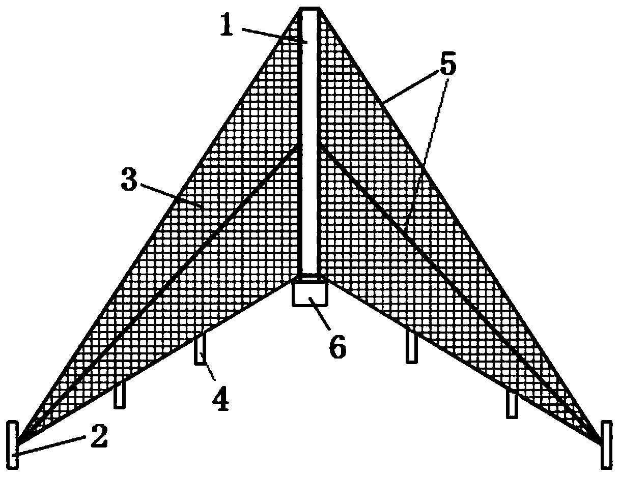
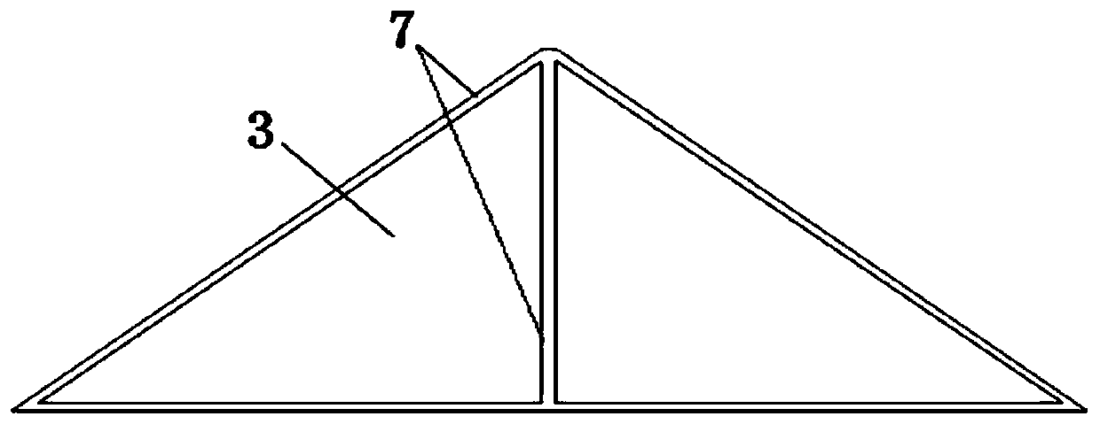
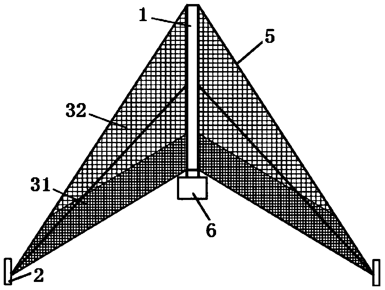
The invention relates to a sand prevention fence device and a sand prevention system. The sand prevention fence device includes a support column, both sides of the support column are respectively provided with at least one fixing pile, a sand prevention net is arranged on the support column, and the sand prevention net is separately connected with the fixing piles at both sides of the support column. Since the fixing pile and the support column are arranged in a triangular shape, the sand prevention net is arranged on the support column and is connected with the fixing piles, so as to form a sand accumulation area, accordingly, the range of sand prevention and resistance can be effectively expanded and the sand accumulation amount can be improved. According to the sand prevention fence device and the sand prevention system, multiple rows of the sand prevention fence devices are arranged in a spaced way and each two adjacent rows of the sand prevention fence devices are subjected to a staggered arrangement, thus a plurality of sand prevention fences having the functions of transporting and guiding sand are used for replacing the original integrated linear sand prevention fence, the sand prevention effects are scattered on each of sand prevention fences instead of the original single linear sand prevention fence, and the sand prevention effects are better.

Description

technical field [0001] The invention relates to the technical field of sandstorm prevention and control, in particular to a sand prevention fence device and a sand prevention system. Background technique [0002] Sandstorm damage is an important factor that seriously restricts the economic and social development of the arid regions in Northwest my country. Wind is the driving force of sand movement, so the prevention and control of wind and sand hazards must first prevent wind. The purpose of the sandstorm prevention and control project is to reduce the wind speed to change the carrying capacity of the airflow, to block the movement of sandstorms and quicksands, so as to protect railways, roads, farmland and towns from sandstorm hazards. [0003] The sand barrier is one of the most important measures in the wind and sand control project. The traditional sand barrier is mainly a high vertical sand barrier, which is made of nylon net, shrub branches, reeds, etc. The shape is ...

Claims


Application Information

Patent Timeline
Patent Type & Authority Patents(China)
IPC IPC(8): E01F7/02E02D3/00A01G17/00
Inventor 肖建华鱼燕萍屈建军黄珊谭立海安志山殷代英
Owner NORTHWEST INST OF ECO ENVIRONMENT & RESOURCES CAS
Learn More