Oil tank structure and unmanned aerial vehicle
A technology for drones and fuel tanks, applied in the field of drones, can solve problems such as changes in the center of drones, and achieve the effect of improving flight stability and hindering changes in the center of gravity of fuel tanks.
- Summary
- Abstract
- Description
- Claims
- Application Information
AI Technical Summary
Problems solved by technology
Method used
Image
Examples
Embodiment 1
[0026] see Figure 4 , the separator 200 in this embodiment is a grid structure 220 , and the grid structure 220 divides the internal space of the fuel tank to form a plurality of vertically arranged cavities 300 . In practical applications, the upper and lower ends of each cavity are opened, and the bottom of each cavity is connected to the liquid outlet (in practical applications, the top of the separator 200 is slightly lower than the tank 100 to facilitate filling gasoline into the tank; the bottom of the separator 200 is set There is a support or gasket structure, and the function of the support or gasket structure is to separate the bottom of the partition 200 from the bottom of the box body 100, so as to prevent the bottom of each cavity from being in close contact with the bottom of the partition 200 and the bottom of the box 100. are closed, so that the cavities cannot communicate with the liquid outlet). With the fuel tank structure of this embodiment, when the fuel...
Embodiment 2
[0030] The fuel tank structure of this embodiment is basically the same as that of Embodiment 1, the difference is that see Figure 5 , the divider of the present embodiment adopts a plurality of independently arranged tubular bodies 210, and each tubular body 210 is vertically arranged and inserted into the box body 100 to separate the inside of the box body 100 to form a plurality of cavities 300; the bottom of each tubular body 210 communicates with the Liquid outlet. The separator of this structure is easier to process and lower in cost, and the independently arranged tubular body structure can flexibly fill oil tank structures of different sizes, and the arrangement is more flexible.
[0031] In practical applications, the shape of the tubular body 210 is preferably a regular hexagonal tubular body (see Figure 5 ), the regular hexagonal tubular body is more convenient and simple to fill, and the fit between the tubular bodies is tighter, the whole structure is more stab...
Embodiment 3
[0034] This embodiment is to optimize the bottom structure of the cavity in embodiment 1 or 2. A flow-blocking structure is provided at the bottom of the cavity to prevent liquid from flowing from the bottom of the cavity into the cavity. The cavity passes through the flow-blocking structure. The structure communicates with the liquid outlet.
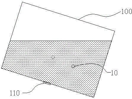
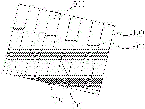
[0035] In this example, see Figure 6 , the blocking structure is selected as the small hole structure 410 . The setting of the small hole structure greatly reduces the liquid circulation velocity at the bottom of each cavity 300. When the fuel tank is tilted (or when the motion state changes suddenly), the center of gravity of the fuel tank changes greatly due to the slow flow of liquid at the bottom of each cavity 300. Slow, can basically guarantee as image 3 status shown.
[0036] When the fuel tank structure of this embodiment is tilted, its center of gravity offset is small, and as time goes by, its center of gravity changes sl...
PUM
 Abstract
Description
Claims
Application Information
 - R&D
- Intellectual Property
- Life Sciences
- Materials
- Tech Scout
- Unparalleled Data Quality
- Higher Quality Content
- 60% Fewer Hallucinations
Browse by: Latest US Patents, China's latest patents, Technical Efficacy Thesaurus, Application Domain, Technology Topic, Popular Technical Reports.
© 2025 PatSnap. All rights reserved.Legal|Privacy policy|Modern Slavery Act Transparency Statement|Sitemap|About US| Contact US: help@patsnap.com


