Material strip packaging machine

A packaging machine and tape technology, applied in the direction of welding/welding/cutting items, manufacturing tools, welding equipment, etc., can solve the problems of increasing production costs, waste materials, reducing production efficiency, etc., to improve production efficiency and prevent feeding errors Problems, Effects of Strong Market Competitiveness

Inactive Publication Date: 2017-01-11
天津市津海伟业科技有限公司
View PDF0 Cites 0 Cited by
  • Summary
  • Abstract
  • Description
  • Claims
  • Application Information

AI Technical Summary

Problems solved by technology

[0003] The existing tape encapsulation machine requires manual feeding, and the wrong feeding direction often results in waste, which reduces production efficiency and increases production costs

Method used


Image

  • Material strip packaging machine

Examples


Embodiment Construction

[0013] For further illustrating the present invention, now cooperate with accompanying drawing to elaborate:

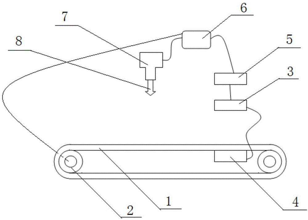
[0014] Such as figure 1 As shown, the material tape packaging machine includes a material rack group, a thermal welding group and a controller 6, and the material rack group includes a conveyor belt 1, a transmission device 2, an optical fiber 3, a reflective optical sensor 4 and a photoelectric converter 5, The transmission device is arranged under the conveyor belt and connected to the controller line, the optical fiber and the reflective light sensor are respectively arranged on the upper and lower sides of the conveyor belt and near the feeding position of the conveyor belt, and the optical fiber is arranged on the reflective optical sensor. Directly above the optical sensor, one end of the optical fiber is connected to the reflective optical sensor, the other end of the optical fiber is connected to the photoelectric converter, the photoelectric converter is conn...


PUM


Abstract

The invention provides a material strip packaging machine. The material strip packaging machine comprises a material frame set, a hot weld unit and a controller. The material frame set comprises a conveying belt, a transmission device, an optical fiber, a reflective optical sensor and a photoelectric converter. The transmission device is arranged below the conveying belt and connected with the controller through a line. The optical fiber and the reflective optical sensor are arranged on the upper side and the lower side of the conveying belt correspondingly and are close to the feeding position of the conveying belt. One end of the optical fiber is connected with the reflective optical sensor, and the other end of the optical fiber is connected with the photoelectric converter. The photoelectric converter is connected with the controller through a line. The hot weld set comprises a servo motor and a welding head. A push rod of the servo motor and the welding head are connected, and the servo motor and the controller are connected through a line. The material strip packaging machine effectively solves the problem of manual feeding errors, the production efficiency is improved, and high market competitiveness is achieved.

Description

technical field [0001] The invention relates to the technical field of mold processing, in particular to a tape packaging machine. Background technique [0002] Most of the existing electronic devices need to set the PIN needle. Especially for integrated chips, the most PIN pins are used. At present, the PIN needle is processed separately when the electronic device is manufactured. The method is to cut the conductive metal material into a strip structure, and then punch out the required PIN structure in a punching machine. For the convenience of transportation, during stamping, some residual material is generally reserved, so that these PIN pins can be connected together to form a material strip, and then the packaging machine is used to package the material strip. [0003] The existing tape encapsulation machine requires manual feeding, and the wrong feeding direction will often cause waste, which reduces production efficiency and increases production costs. Contents of...

Claims


Application Information

Patent Timeline
IPC IPC(8): B23K31/02B23K101/16
CPCB23K31/02
Inventor 匡志利
Owner 天津市津海伟业科技有限公司
Why Eureka
Try Eureka