
Solar module detection method

A technology of a solar module and a detection method, which is applied in the detection field, can solve the problems of time-consuming and labor-intensive, poor detection efficiency, etc., and achieves the effect of improving the detection efficiency and solving the time-consuming and labor-intensive problems.

Inactive Publication Date: 2017-01-04
ENLI TECH
View PDF0 Cites 2 Cited by
  • Summary
  • Abstract
  • Description
  • Claims
  • Application Information

AI Technical Summary

Problems solved by technology

In this way, when testing the solar modules, the above-mentioned method of testing each solar cell one by one has poor detection efficiency, which will cause time-consuming and labor-consuming problems.

Method used


Image

  • Solar module detection method
  • Solar module detection method
  • Solar module detection method

Examples


no. 1 example

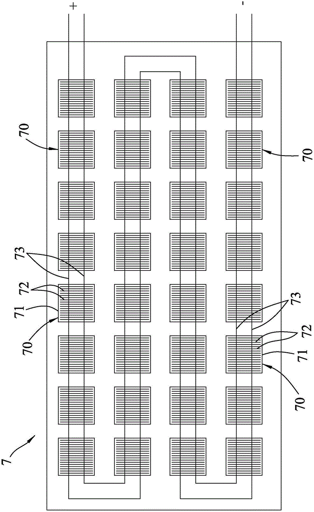
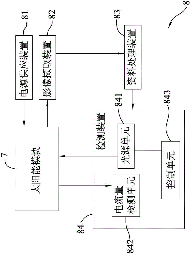
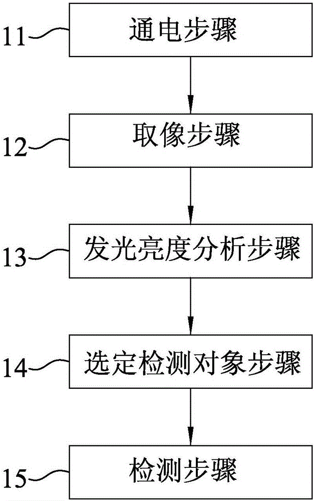
[0038] refer to figure 1 , 2 , 3, a first embodiment of detection method of the present invention, comprises the following steps:

[0039] Step 11 of electrifying: apply a direct current to the solar module 7 through the power supply device 81 to make the solar cell 70 emit light. This approach is also called electroluminescence (Electroluminescence; EL).

[0040] Perform image capture step 12: capture and output several images respectively corresponding to the solar cells 70 through the image capture device 82 .

[0041]Perform luminous brightness analysis step 13: analyze the luminous luminance of the image output by the image capture device 82 through a data processing device 83, and output several luminous luminance values ​​respectively corresponding to the images, and several corresponding to the Image number information.

[0042] Wherein, the serial number information may be a serial number determined according to the arrangement order of the solar cells 70 connecte...


PUM


Abstract

A solar module detection method is used to detect the solar cells of a solar module. The detection method comprises a powering-on step: making solar cells electroluminescent; an image capture step: capturing an image of the solar cells emitting light; a luminous intensity analysis step: analyzing the captured image; a detection object selection step: finding out solar cells with low luminous intensity; and a detection step: detecting the solar cells with low luminous intensity. If a solar cell is of lower luminous intensity, the photoelectric conversion efficiency of the solar cell is poorer, and the current produced by the solar cell is lower. In the detection step, only a few decisive solar cells are detected. Thus, there is no need to detect all the solar cells in the detection method, the detection efficiency is improved, and time and labor are saved.

Description

[0001] 【Technical field】 [0002] The invention relates to a detection method, in particular to a detection method of a solar module. [0003] 【Background technique】 [0004] A solar cell is a battery that converts light energy into electrical energy for use. In use, several solar cells are usually arranged in a two-dimensional array between two plates spaced up and down, and the solar cells are connected by welding ribbons. They are electrically connected to each other, and the solar cells are covered by the encapsulation material to be packaged into a solar module. Afterwards, related performance tests will be carried out on the solar module, such as through spectral response (Spectral Responsivity, SR) testing, to understand the photoelectric conversion capability of the solar cell after packaging. [0005] However, in the existing detection methods, each solar cell of the solar module is detected one by one. On the other hand, due to the increasing size of the current sol...

Claims


Application Information

Patent Timeline
Patent Type & Authority Applications(China)
IPC IPC(8): H02S50/10
CPCY02E10/50
Inventor 柯历亚廖华贤陈泓展谢世章林启清林高同吴恒信陈震伟秦海岩
Owner ENLI TECH
Learn More