
mobile terminal

A mobile terminal and input terminal technology, applied in the field of mobile communication, can solve problems such as poor signal and affecting the use of mobile terminals, and achieve the effect of avoiding electromagnetic field leakage and improving heat dissipation efficiency

Active Publication Date: 2019-01-15
SHANGHAI TRANSSION CO LTD
View PDF5 Cites 0 Cited by
  • Summary
  • Abstract
  • Description
  • Claims
  • Application Information

AI Technical Summary

Problems solved by technology

[0006] However, the mobile terminal adopting the above-mentioned dual charging chip solution often has the problem of poor signal, which affects the use of the mobile terminal.

Method used


Image

  • mobile terminal

Examples


Embodiment Construction

[0021] The specific implementation manners of the mobile terminal provided by the present invention will be described in detail below in conjunction with the accompanying drawings.

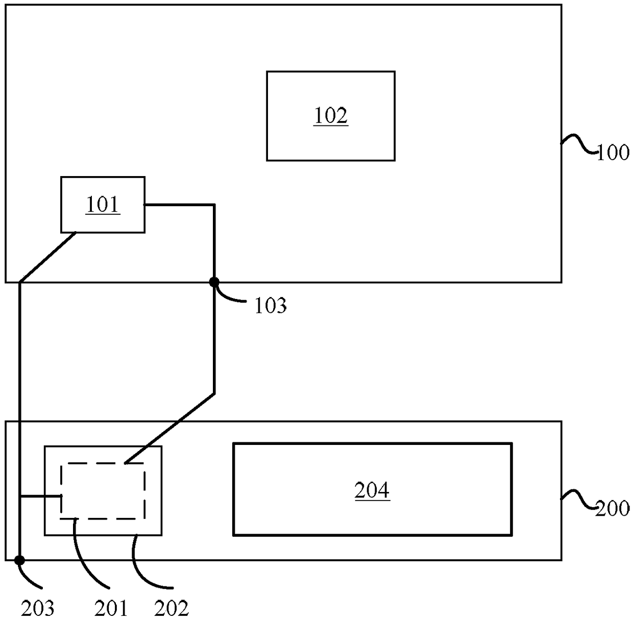
[0022] Please refer to figure 1 It is a structural schematic diagram of the mobile terminal.

[0023] The mobile terminal includes: a first circuit board 100; a first charging chip 101 arranged on the first circuit board 100; a second circuit board 200; a shielding cover 202 arranged on the second circuit board 200; The second charging chip 201 surrounded by the shielding cover 202 on the circuit board 200 is connected in parallel with the first charging chip 101 . Since the second charging chip 201 is located in the shielding case 201 and cannot be seen, figure 1 Indicated by a dotted line.

[0024] As a specific embodiment of the present invention, the first circuit board 100 is a main board of a mobile terminal, and has a relatively large area. The first circuit board 100 may be provided wit...


PUM


Abstract

Disclosed is a mobile terminal. The mobile terminal comprises a first circuit board, a first charging chip arranged on the first circuit board, a second circuit board, a shielding cover arranged on the second circuit board, and at least one second charging chip which is arranged on the second circuit board and surrounded by the shielding cover, wherein the second charging chip is connected with the first charging chip in parallel. By adopting of the mobile terminal, the charging time can be shortened and temperature rise can be lowered while influence to sensitivity of an antenna is reduced.

Description

technical field [0001] The present invention relates to the field of mobile communication, in particular to a mobile terminal. Background technique [0002] As the battery capacity of the mobile terminal increases, the charging time of the battery becomes longer and longer. In the prior art, dual charging chips are used to quickly charge the battery, which can effectively shorten the charging time of the battery. [0003] The charging chip is generally arranged on the main board of the mobile terminal. During the charging process, the temperature of the charging chip will rise, resulting in a relatively large temperature rise of the main board. For the charging scheme with dual charging chips, the temperature rise of the main board is even greater. [0004] The current mainstream heat dissipation method is to use water-cooled heat-conducting copper tube technology to conduct heat to other places through copper tubes for heat dissipation, but the cost is high and the risk of ...

Claims


Application Information

Patent Timeline
Patent Type & Authority Patents(China)
IPC IPC(8): H02J7/00H02J50/20
CPCH02J7/025
Inventor 王肖伟吕磊李肇光
Owner SHANGHAI TRANSSION CO LTD
Learn More