
Design method for front landing gear of full-maneuverable mechanical model and simplified structure

A technology of nose landing gear and mechanical model, applied in design optimization/simulation, calculation, special data processing application, etc., can solve the problem of not meeting the requirements of mechanical performance curve, high cost of nose landing gear buffer, and limited space for nose landing gear size and other problems, to achieve the effect of easy test parameter requirements, clear constraint requirements, low manufacturing cost and process requirements

Active Publication Date: 2017-01-04
XIAN AIRCRAFT DESIGN INST OF AVIATION IND OF CHINA
View PDF0 Cites 1 Cited by
  • Summary
  • Abstract
  • Description
  • Claims
  • Application Information

AI Technical Summary

Problems solved by technology

[0003] (1) The design of the front model landing gear is exactly the same as that of the real aircraft. The cost of the front landing gear buffer is high and the structure is complicated; at the same time, due to the limited size and space of the front landing gear of the model, the processing requirements are extremely high;
[0004] (2) The front landing gear of the model is a combination of a single rod and a tire, without a buffer part. In the test, the front landing gear only provides support and cannot meet the requirements of the mechanical performance curve in the test

Method used


Image

  • Design method for front landing gear of full-maneuverable mechanical model and simplified structure
  • Design method for front landing gear of full-maneuverable mechanical model and simplified structure
  • Design method for front landing gear of full-maneuverable mechanical model and simplified structure

Examples


Embodiment Construction

[0024] In order to make the objectives, technical solutions and advantages of the present invention clearer, the technical solutions in the embodiments of the present invention will be described in more detail below in conjunction with the drawings in the embodiments of the present invention. In the drawings, the same or similar reference numerals denote the same or similar elements or elements having the same or similar functions throughout. The described embodiments are some, but not all, embodiments of the invention. The embodiments described below by referring to the figures are exemplary and are intended to explain the present invention and should not be construed as limiting the present invention. Based on the embodiments of the present invention, all other embodiments obtained by persons of ordinary skill in the art without making creative efforts belong to the protection scope of the present invention. Embodiments of the present invention will be described in detail b...


PUM


Abstract

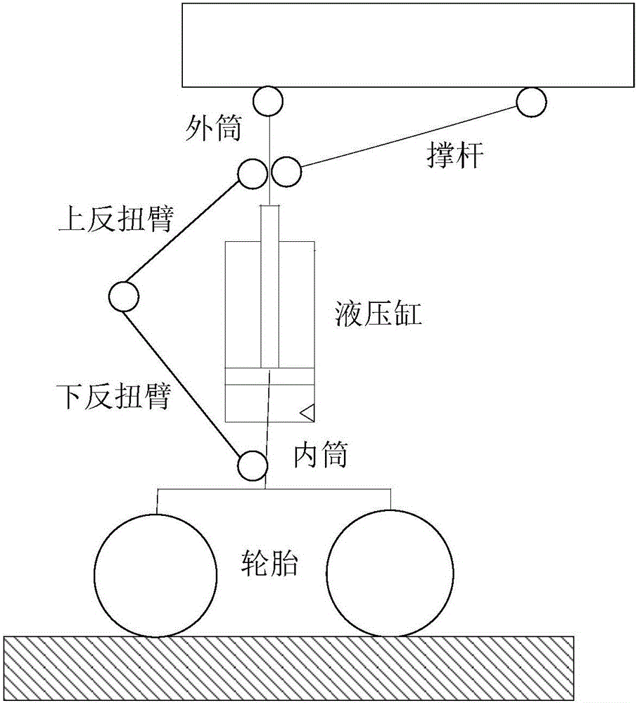
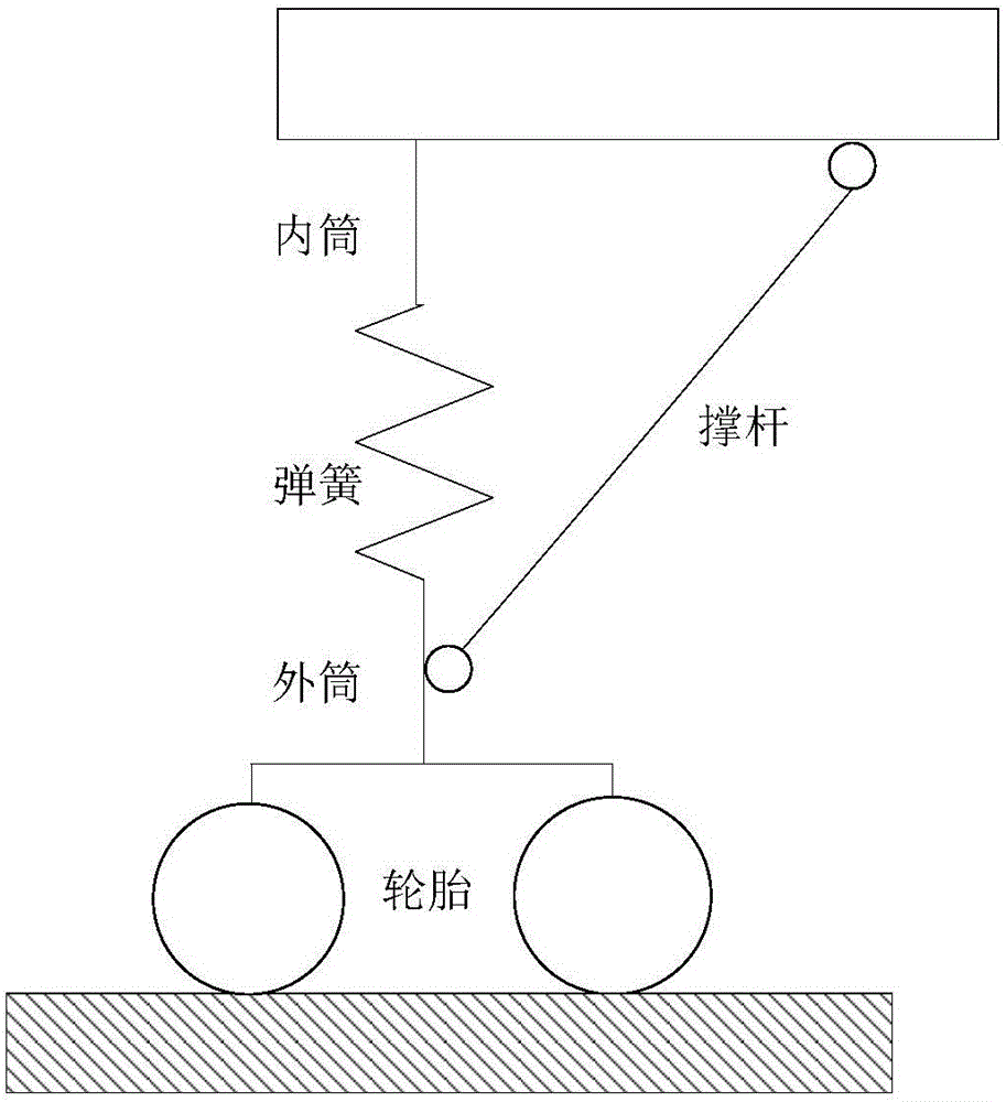
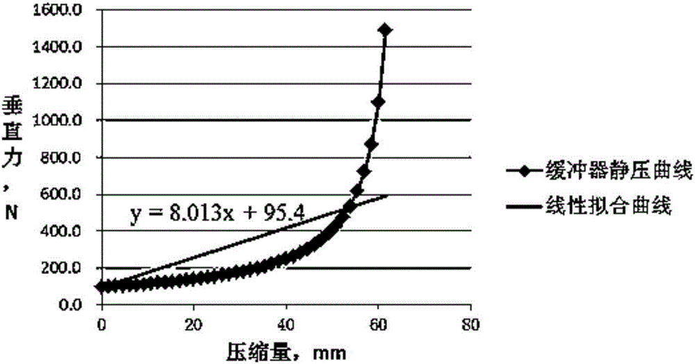
The invention relates to a design method for a front landing gear of a full-maneuverable mechanical model. The design method comprises the following steps: I, acquiring a design size of the front landing gear of the full-maneuverable mechanical model according to the size of a real front landing gear and a predetermined shrink ratio; II, acquiring a force transfer structure of the front landing gear of the model according to a force transfer structure of the real front landing gear, and calculating the mechanical property of the force transfer structure of the simplified front landing gear in a simulation way; III, performing fitting according to the performance parameters of a hydraulic buffer and a tire in the real front landing gear to obtain a spring rigidity coefficient and a tire performance parameter in the simplified structure of the front landing gear; IV, recalculating the spring size and the tire size according to the mechanical property obtained in the step II and the spring rigidity coefficient and the tire performance parameter obtained in the step III; V, performing iterative optimization to obtain an optimal size of the front landing gear of the full-maneuverable mechanical model. Adopting the design method for the front landing gear of the full-maneuverable mechanical model ensures completely that the force transfer structure and the force transfer characteristic can meet the dynamic test requirement.

Description

technical field [0001] The invention belongs to the technical field of aircraft structure strength tests, and in particular relates to a design method of a nose landing gear of a dynamic model of the whole aircraft and a simplified structure. Background technique [0002] The nose landing gear is an accessory device used to support the aircraft and move on the ground when the lower part of the aircraft is used for take-off and landing or ground taxiing. In the previous dynamic model design, the design of the front landing gear buffer has the following methods: [0003] (1) The design of the front model landing gear is exactly the same as that of the real aircraft. The cost of the front landing gear buffer is high and the structure is complicated; at the same time, due to the limited size and space of the front landing gear of the model, the processing requirements are extremely high; [0004] (2) The front landing gear of the model is a combination of a single rod and a tir...

Claims


Application Information

Patent Timeline
IPC IPC(8): G06F17/50
CPCG06F30/15G06F30/20
Inventor 金鑫何康乐杜瑞研刘宇
Owner XIAN AIRCRAFT DESIGN INST OF AVIATION IND OF CHINA
Learn More