
Polarization imaging principle-based polarization maintaining fiber axis alignment device and axis alignment method

A polarization-maintaining optical fiber and imaging principle technology, applied in polarized optical fiber, cladding optical fiber, installation, etc., can solve the problems of high environmental requirements and slow axis fixing speed, and achieve the effect of fast axis fixing speed and guaranteed coaxiality

Inactive Publication Date: 2017-01-04
HARBIN ENG UNIV
View PDF3 Cites 4 Cited by
  • Summary
  • Abstract
  • Description
  • Claims
  • Application Information

AI Technical Summary

Problems solved by technology

This method has high requirements for the environment and slow axis fixing speed, and is not suitable for polarization-maintaining optical fibers with small fluctuations in refractive index such as elliptical inner cladding

Method used


Image

  • Polarization imaging principle-based polarization maintaining fiber axis alignment device and axis alignment method
  • Polarization imaging principle-based polarization maintaining fiber axis alignment device and axis alignment method
  • Polarization imaging principle-based polarization maintaining fiber axis alignment device and axis alignment method

Examples


Embodiment Construction

[0022] The present invention will be described in more detail below with examples in conjunction with the accompanying drawings.

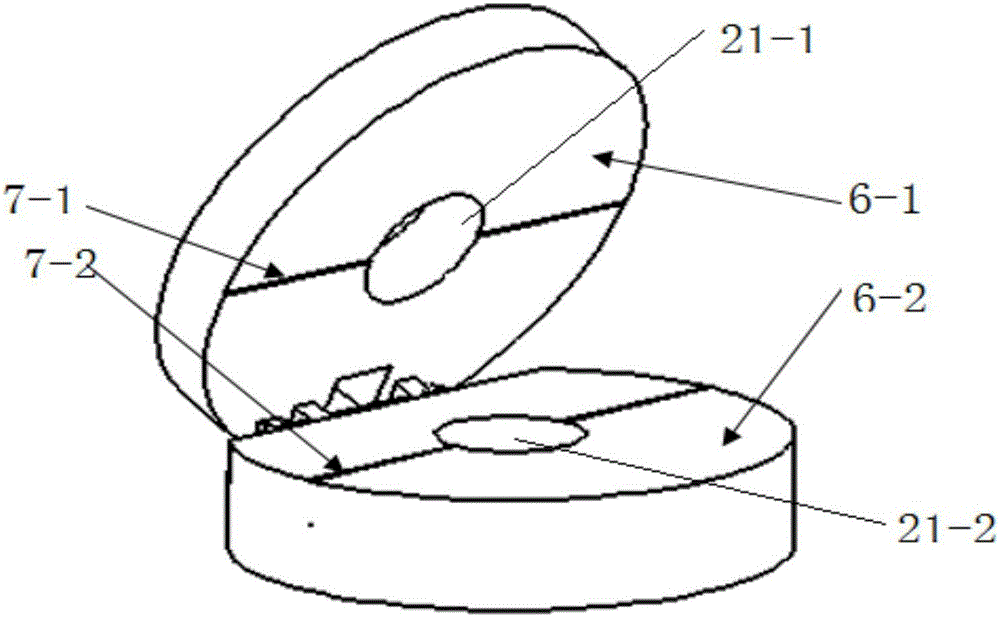
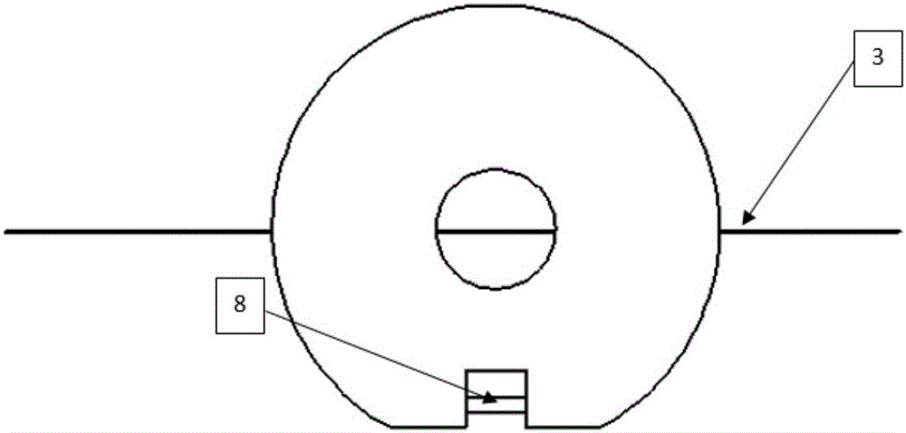
[0023] combine figure 1 with figure 2 , the polarization-maintaining optical fiber axis fixing device based on the polarization imaging principle of the present invention comprises an upper optical fiber limiting plate 6-1 and a lower optical fiber limiting plate 6-2, one side of the upper and lower optical fiber limiting plates is connected by a cylindrical shaft 8, and the upper and lower optical fibers There are circular holes 21-1 and 21-2 on the limiting plate, and semicircular grooves 7-1 and 7-2 passing through the circular holes are opened on the upper and lower optical fiber limiting plates. The diameters of the semicircular slots are equal. The semicircular grooves on the upper and lower optical fiber limiting plates have been polished.

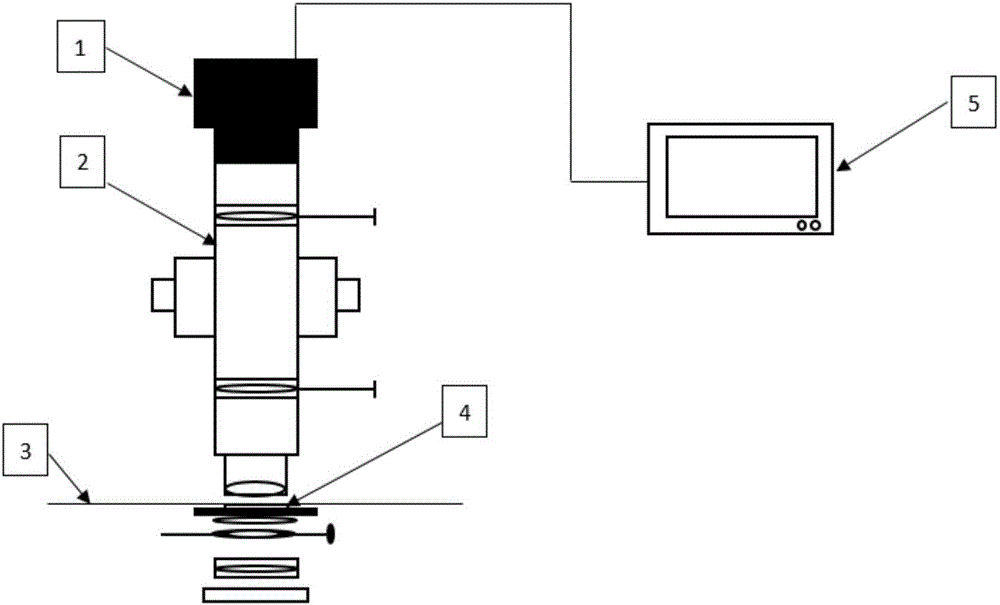
[0024] combine image 3 with Figure 4 , the axis-fixing system used in the polarization-mainta...


PUM


Abstract

The invention provides a polarization imaging principle-based polarization maintaining fiber axis alignment device and an axis alignment method. The device comprises an upper fiber limiting plate and a lower fiber limiting plate, wherein one side of the upper fiber limiting plate and one side of the lower fiber limiting plate are connected through a cylindrical shaft; circular holes are formed in the upper and lower fiber limiting plates; semicircular grooves penetrating through the circular holes are formed in the upper and lower fiber limiting plates; the diameters of the semicircular grooves in the upper and lower fiber limiting plates are equal. A polarization maintaining fiber is placed on the axis alignment device. A polarization microscope is turned on, a focal length of the microscope is adjusted to enable the polarization maintaining fiber to present a polarization interference image of an inner cladding and a fiber core on the microscope, and a distinct image is acquired by virtue of a CCD (charge coupled device) camera. The polarization maintaining fiber is rotated to obtain characteristic images of an internal structure of the polarization maintaining fiber under different azimuths, and a characteristic curve is established through a corresponding relationship between a characteristic value and a rotating azimuth, thereby implementing axis alignment of the polarization maintaining fiber. The device for axis alignment of the polarization maintaining fiber has the advantages of high axis alignment speed, high accuracy and applicability to polarization maintaining fibers of different types.

Description

technical field [0001] The invention relates to a polarization-maintaining optical fiber axis fixing device and an axis fixing method. Background technique [0002] Polarization-maintaining fiber has been widely researched and applied in the field of optical fiber communication and sensing due to its strong polarization-maintaining ability for linearly polarized light and good compatibility with general single-mode fiber. In recent years, polarization-maintaining fiber devices such as polarization-maintaining fiber couplers, polarization-maintaining fiber polarizers, and polarization-maintaining fiber connectors have been widely used. The direction of the polarization axis of the polarized fiber. [0003] The most widely used polarization-maintaining optical fiber axis-fixing method is the optical axis-fixing method. The optical axis fixing method can be divided into two methods: vertical axis fixing and horizontal axis fixing according to the light transmission and observ...

Claims


Application Information

Patent Timeline
Patent Type & Authority Applications(China)
IPC IPC(8): G02B6/024G02B7/00
CPCG02B6/024G02B7/00
Inventor 耿涛周宇闫奇毕谣孙伟民佟成国麻镇宇杨帆
Owner HARBIN ENG UNIV
Learn More