
Sludge roller external heat drying and circulating fluidized bed incineration integration and tail gas cleanup device

A tail gas purification device and circulating fluidized bed technology, applied in dehydration/drying/concentrated sludge treatment, incinerator, combustion method, etc. 40% and other problems, to achieve the effect of simple structure, lower operating costs, and reduced power consumption

Active Publication Date: 2017-01-04
HARBIN INST OF TECH
View PDF14 Cites 25 Cited by
  • Summary
  • Abstract
  • Description
  • Claims
  • Application Information

AI Technical Summary

Problems solved by technology

There are many problems in the existing domestic sludge drying and incineration technology, for example: the patent applied by Zhejiang Sanlian Environmental Protection Machinery Equipment Co., Ltd., a built-in comprehensive sludge drying and incineration system and sludge drying and incineration method, application number: 201410329596 . X, although the intermediate circulation link is omitted to avoid the leakage of odor, it needs to add pulverized coal to the sludge, and it needs to be burned twice, so the operating cost is high; the utility model patent rotary kiln sludge applied by Yu Hongtao Thermal drying device, patent number: 201020617754.9, adopts a single-stage drying method, and there are problems such as too long a rotary kiln body, too large an area, and the sludge moisture can only be reduced to about 40% in general, and these patents are very harmful to incineration. Exhaust is not treated

Method used


Image

  • Sludge roller external heat drying and circulating fluidized bed incineration integration and tail gas cleanup device

Examples


Embodiment Construction

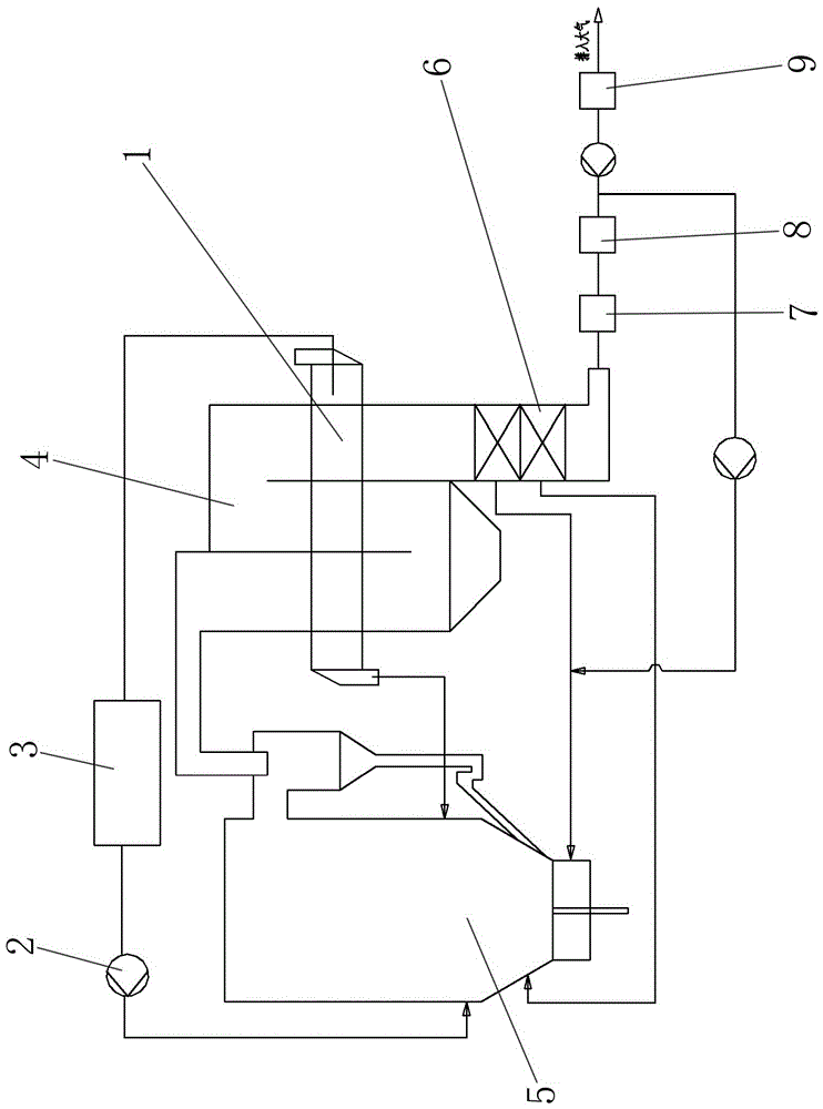
[0008] refer to figure 1 , a sludge drum external heat drying and circulating fluidized bed incineration integration and tail gas purification device, which includes a circulating fluidized bed, a drying system and a tail gas purification system, the drying system includes a rotary kiln drum 1, a fan 2 and The condenser 3 and the rotary kiln drum 1 are interspersed on the tail flue 4 of the circulating fluidized bed. The rotary kiln drum 1 is connected to the tail flue 4 in rotation. The high-temperature flue gas directly heats the outer wall of the rotary kiln drum 1, and indirectly dries the wet sludge in the rotary kiln drum 1. The tail flue 4 adopts an S-shaped rotary circulation structure to increase the drying area of ​​the rotary kiln drum 1. The two ends of rotary kiln drum 1 are respectively provided with feed inlet and discharge outlet. One end of the discharge outlet of rotary kiln drum 1 is inclined downward by three to five degrees, making it easier to unload the ...


PUM


Abstract

The invention discloses a sludge roller external heat drying and circulating fluidized bed incineration integration and tail gas cleanup device, and belongs to the technical field of sludge incineration treatment. The problem existing in an existing sludge drying and incineration technology is solved. The device comprises a circulating fluidized bed, a drying system and a tail gas cleanup system. The drying system comprises a rotary kiln roller, a fan and a condenser. The rotary kiln roller is inserted into a tail flue of the circulating fluidized bed in a penetrating mode. After water vapor and bed smell generated in the sludge drying process are condensed and water is removed, the water vapor and bed smell are supplied to a hearth of the circulating fluidized bed to be combusted for deodorization; two air preheaters are arranged inside the tail flue and connected with a primary tuyere and a secondary tuyere arranged in the hearth of the circulating fluidized bed respectively. The tail gas cleanup system comprises an activated carbon injection device, a cloth bag dust remover and a wet desulphurization system which are sequentially arranged behind the air preheaters. A gas conveying pipe is arranged between the cloth bag dust remover and the wet desulphurization system to be connected with the primary tuyere. The device is used for sludge drying and incineration.

Description

technical field [0001] The invention belongs to the technical field of sludge incineration treatment, and in particular relates to a sludge drum external heat drying and circulating fluidized bed incineration integration and tail gas purification device. Background technique [0002] With the continuous improvement of my country's economic level, the amount of sewage treatment has also increased significantly. At present, there are nearly 4,000 sewage treatment plants in my country, which produce about 55 million tons of wet sludge with 80% water content every year, and nearly 60% of the pollutants in sewage It is concentrated in the sludge, so the harmless treatment of sludge needs to be solved urgently. At present, the main method of domestic sludge disposal is direct landfill, and very few use incineration. Because landfill needs to occupy a large amount of land, and may cause pollution to groundwater, sludge incineration is a reduction, stabilization, and harmless method....

Claims


Application Information

Patent Timeline
IPC IPC(8): F23G7/00F23G5/04F23G5/30F23G5/46C02F11/12
CPCF23G5/04F23G5/30F23G5/46F23G7/001F23G2201/101F23G2203/50F23G2206/10
Inventor 别如山顾文波纪晓瑜陈佩房文轩
Owner HARBIN INST OF TECH
Learn More