Device capable of automatically adjusting rigidity of flexible blade of wind turbine

A technology of automatic adjustment and blade stiffness, which is applied to wind turbines, wind turbines, engines, etc. in the same direction as the wind, can solve the problems of blade fatigue damage, blade bending and torsion fracture, etc., and achieve the effect of changing rigidity

Inactive Publication Date: 2017-01-04
XIANGTAN UNIV
View PDF6 Cites 6 Cited by
  • Summary
  • Abstract
  • Description
  • Claims
  • Application Information

AI Technical Summary

Problems solved by technology

[0006] In order to solve the technical problems that the flexible blades used in the existing wind power generation equipment are likely to cause fatigue damage to the blades and easily generate cracks to cause ben...

Method used


Image

  • Device capable of automatically adjusting rigidity of flexible blade of wind turbine
  • Device capable of automatically adjusting rigidity of flexible blade of wind turbine
  • Device capable of automatically adjusting rigidity of flexible blade of wind turbine

Examples


Embodiment 1

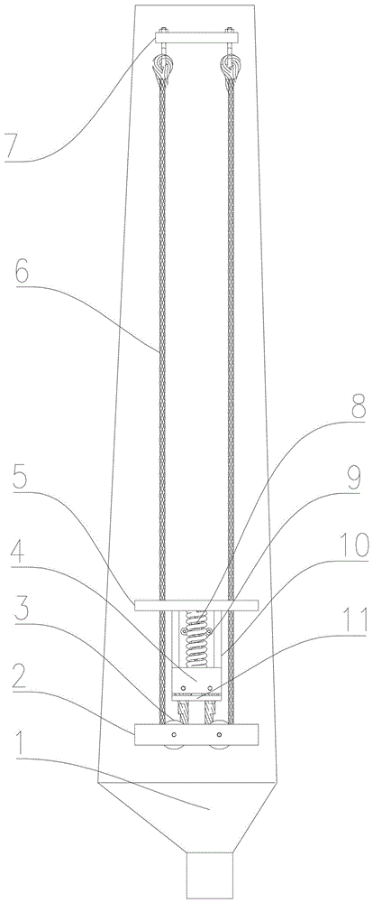
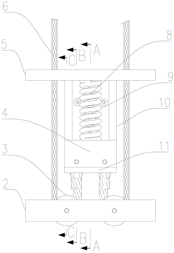
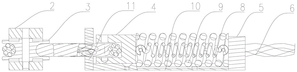
[0025] Embodiment 1, refer to Figure 1 to Figure 3 , the present invention includes a support block 2, a fixed pulley 3, an inertia block 4, a front end fixed block 5, a steel wire rope 6, a tail end fixed block 7, a tension spring 8, a compression spring 9 and a linear guide rail 10; the support block 2, the front end The fixed block 5 and the tail end fixed block 7 are respectively arranged side by side on the same side of the flexible blade 1 from inside to outside, and a linear guide rail 10 is fixed on the flexible blade 1 between the support block 2 and the front end fixed block 5, The inertia block 4 is installed on the linear guide rail 10; two fixed pulleys 3 are arranged on the support block 2; one end of the tension spring 8 and the compression spring 9 are respectively connected with the front end fixed block 5, and the other ends are respectively connected with the fixed block 5 installed on the straight line The inertia block 4 on the guide rail 10 is connected;...

Embodiment 2

[0026] Embodiment 2, refer to Figure 1 to Figure 3 , the support block 2 of the present invention is installed at a position close to the root of the flexible blade 1, and the front end fixed block 5 is installed on one side of the support block 2, and the front end fixed block 5 is connected and fixed with one end of the linear guide rail 10; the support block 2, the front end Both the fixed block 5 and the linear guide rail 10 are respectively fixed on the flexible blade 1 . The rest are combined with another arbitrary embodiment of the present invention or two or more embodiments.

Embodiment 3

[0027] Embodiment 3, refer to Figure 1 to Figure 3, the tail end fixing block 7 of the present invention is installed on the outer end of the flexible blade 1 near the tail end of the blade tip, the bottom of the tail end fixing block 7 is fixed on the flexible blade 1, and a filling material is arranged on the outer periphery of the tail end fixing block 7 to seal it The surrounding is fastened so that it is integrated with the blade tip part of the flexible blade 1 to prevent long-term erosion and cause the product to fall off. The rest are combined with another arbitrary embodiment of the present invention or two or more embodiments.


PUM


Abstract

The invention discloses a device capable of automatically adjusting the rigidity of a flexible blade of a wind turbine. The device aims at mainly solving the technical problems of easy fatigue and damage and the like in the existing flexible blade. The device is charachterized in that the two ends of an extension spring (8) and a compression spring (9) are respectively connected with a front-end fixed block (5) and a moving inertial block (4) embedded in a linear guide rail (10); one end of each steel wire rope (6) is connected with the inertial block (4); the steel wire rope (6) bypasses a fixed pulley (3) fixed on a supporting block (2), and then penetrates through the front-end fixed block (5) to be connected with a tail-end fixed block (7); two steel wire ropes (6) are symmetrically distributed at the two sides of the inertial block (4). The device disclosed by the invention has the advantages that the structure is simple, the manufacture and the maintenance are convenient, the rigidity of the flexible blade of the wind turbine can be automatically adjusted along with the change of wind speed. In addition, the device has the advantage of expanding the wind-speed range for operation of the wind turbine, and is mainly used for the field of blades of wind-power generation equipment.

Description

technical field [0001] The invention belongs to the technical field of wind power generation, in particular to a device capable of automatically adjusting the stiffness of flexible blades of a wind turbine. Background technique [0002] Wind energy is the new energy with the most development value and huge reserves, so how to efficiently use wind energy to generate electricity has always been the focus and hot spot of new energy development. According to the investigation and research of our country's wind farms by relevant researchers, the development of breeze-type wind turbines suitable for land use is the development direction of my country's wind power industry, and it has become a consensus to improve the power generation performance of breeze. The main way to improve the performance of wind power generation is to change the blade structure and improve the structural dynamic performance. According to the principles of bionics and the needs of wind power development, fl...

Claims


Application Information

Patent Timeline
IPC IPC(8): F03D1/06
CPCF03D1/0675F05B2240/311Y02E10/72Y02P70/50
Inventor 龚曙光吴海斌谢桂兰张建平吴辉
Owner XIANGTAN UNIV
Why Eureka
Try Eureka