
Construction method of directional hole in upward penetration layer on top plate for gas drainage in underground coal mine

A gas drainage and construction method technology, which is applied in the direction of gas discharge, directional drilling, mining equipment, etc., can solve the problems of short extension distance of fracture zone, long construction period, low drilling efficiency, etc. The effect of large hole coverage area and high drilling efficiency

Active Publication Date: 2018-06-19
XIAN RES INST OF CHINA COAL TECH& ENG GROUP CORP
View PDF7 Cites 0 Cited by
  • Summary
  • Abstract
  • Description
  • Claims
  • Application Information

AI Technical Summary

Problems solved by technology

[0006] The purpose of the present invention is to provide a coal mine underground mining gas drainage system for the problems of small aperture, short extension distance of the fissure zone, low drilling efficiency, high cost, and long construction period in existing coal mine gas drainage drilling holes. Construction Method of Oriented Hole in Upward Penetrating Layer on Mining Roof

Method used


Image

  • Construction method of directional hole in upward penetration layer on top plate for gas drainage in underground coal mine
  • Construction method of directional hole in upward penetration layer on top plate for gas drainage in underground coal mine
  • Construction method of directional hole in upward penetration layer on top plate for gas drainage in underground coal mine

Examples


Embodiment

[0033] The implementation of the present invention will be described in detail below through examples and in conjunction with the accompanying drawings. in,

[0034] Example:

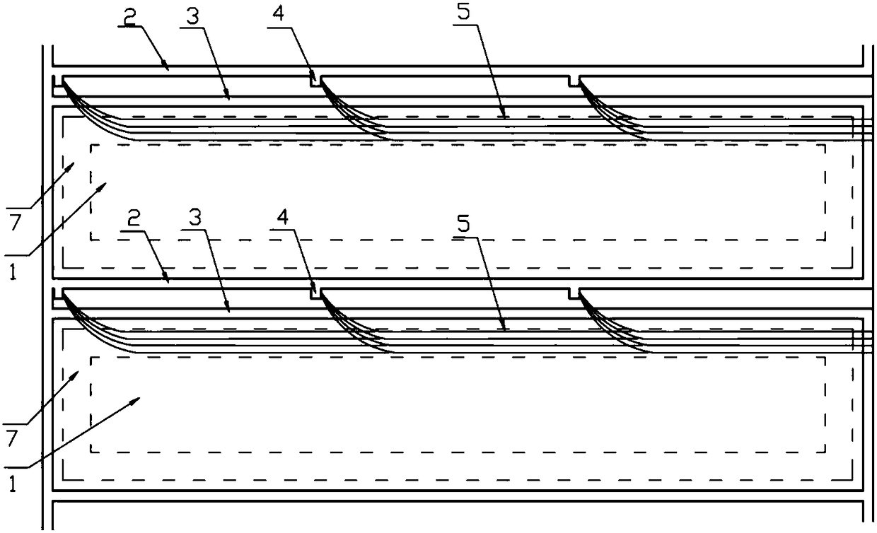
[0035] see figure 1 , figure 2 , a method for constructing directional holes in the upward penetration layer on the roof of coal mine underground mining gas drainage, characterized in that it includes the following steps:

[0036] Step 1: Drill site 4 preparation. A plurality of drilling sites 4 have been developed in the wind tunnel 2 of the adjacent working face of the working face 1 to be mined in the underground, and the distance between the adjacent drilling sites 4 is equal to the horizontal projection length of the directional hole 5 of the directional stabilizing hole section c of the upward penetration layer on the top plate .

[0037] Step 2: Drill hole design. According to the mine coal seam roof occurrence and mining plan, the existing model simulation analysis and theoretical formula...


PUM


Abstract

The invention relates to a method for constructing a directional hole in an upward penetration layer on an underground mining gas drainage roof of a coal mine. The present invention utilizes the drilling field that has been excavated into the air roadway at the adjacent working face of the working face to be mined, and utilizes equipment such as pilot directional drilling tools and impact compound reaming drilling tools, and adopts multi-stage rotary reaming technology, sliding directional drilling technology, and composite drilling technology. Directional drilling technology and percussion compound reaming technology drilled to obtain directional holes on the roof through the layer, so that they can enter the roof mining fracture zone and abscission zone in advance, and extend for a long distance and large diameter. After the drilling construction, when the working face to be mined is recovered, the upward fissures formed by the mining on the roof layer are connected with the directional holes in the upward penetration layer on the roof. The use of dynamic gas drainage solves the shortcomings of the current mining gas drainage drilling, such as small hole diameter, short extension distance of the fissure zone, low drilling efficiency, high cost, and long construction period, and improves the effect of mining gas drainage.

Description

technical field [0001] The invention relates to a directional hole construction method and equipment, which belong to the field of coal mine underground tunnel drilling, in particular to a method for constructing directional holes on an upward penetration layer on an underground gas drainage roof of a coal mine. Background technique [0002] Coal mine gas disaster is one of the main safety disasters in the process of mine construction and mine production. It is extremely destructive and brings great hidden dangers and losses to coal mine safety production. In recent years, this coal seam gas pre-drainage technology has significantly reduced the coal seam gas content in the working face. However, with the development of comprehensive mechanized coal mining technology in coal mines, the advancement of the working face has accelerated, and the amount of gas emitted during mining has increased sharply, which has become a constraint for some mines. A key factor in safe and effici...

Claims


Application Information

Patent Timeline
Patent Type & Authority Patents(China)
IPC IPC(8): E21B7/04E21B7/06E21B10/32E21B33/13E21F7/00
CPCE21B7/04E21B7/06E21B10/32E21B33/13E21F7/00
Inventor 李泉新方俊许超刘建林曹明赵建国王四一王鲜
Owner XIAN RES INST OF CHINA COAL TECH& ENG GROUP CORP
Learn More