Micro hanging type drying equipment
A drying equipment and hanging technology, which is applied to other drying equipment, household clothes dryers, textiles and papermaking, etc., can solve problems such as failure safety, liquid leakage, hidden dangers, etc., to improve load capacity and improve Stability, remarkable effect
- Summary
- Abstract
- Description
- Claims
- Application Information
AI Technical Summary
Problems solved by technology
Method used
Image
Examples
Embodiment 1
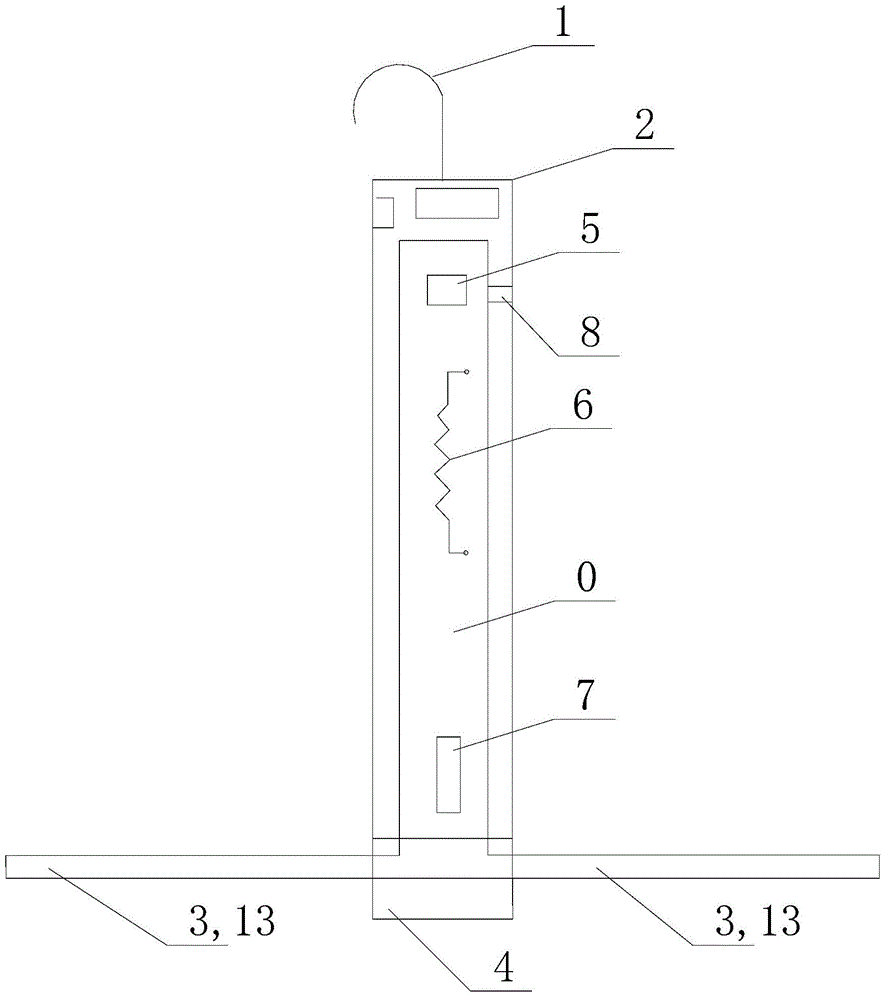
[0043] like figure 1As shown, in this embodiment, the bottom of the mounting portion 2 is provided with a relatively rotatable base 4 , and the mounting portion 3 is mounted on the base 4 so that the mounting portion 3 can rotate together with the base 4 . Through the above arrangement, during the working process of the drying device, the carrying part drives the clothes to rotate horizontally, so as to form natural wind and achieve the purpose of speeding up the drying rate of the clothes.
[0044] In this embodiment, the bottom of the mounting part 2 is provided with a base 4 for plug connection, so that the base 4 can be relatively rotatably mounted on the mounting part 2; preferably, the base 4 covers the bottom of the cavity 0, so that the cavity 0 airtight setting. The mounting part 2 is provided with a motor 7 that drives the base 4 to rotate, the body of the motor 7 is fixed with the mounting part 2, and the rotating end is fixedly connected with the base 4, so that t...
Embodiment 2
[0048] like Figure 1 to Figure 3 As shown, in this embodiment, the connecting end of the mounting portion 3 connected to the base 4 is open and the other end is sealed; the opening connects the cavity 0 with the air duct 13 formed by the mounting portion 3, and the mounting portion 3 At least one air outlet 9 is arranged so that the drying airflow formed in the mounting part 2 flows out from the air outlet 13 to dry the clothes mounted on the mounting part 3 .
[0049] preferably, as image 3 As shown, in this embodiment, a plurality of air outlets 9 are arranged at equal intervals on the lower side of the mounting portion 3, so that the drying airflow is blown downward to blow directly onto the loaded clothes, so that the clothes and the drying airflow can be directly blown out. contact and improve drying efficiency.
[0050] Of course, in this application, in order to improve the drying efficiency, a plurality of air outlets (not indicated in the accompanying drawings) ca...
Embodiment 3
[0053] like figure 1 and 2 As shown, in this embodiment, the mounting portion 3 is rotatably connected to the base 4 via the hinge 12 , so that the mounting portion 3 has a first state in which the mounting portion 3 is perpendicular to the mounting portion 2 for the clothes to be mounted on, and is parallel to the mounting portion 2 The second state of being folded for easy storage and placement. Therefore, the carrying portion can be folded and stored, so as to reduce the space occupied by the drying equipment.
[0054] like figure 2 As shown, in this embodiment, the mounting portion 2 is composed of a hollow columnar structure, and the outer side wall of the mounting portion 2 is correspondingly provided with a groove 10 for the mounting portion 3 to be folded and stored, so that the mounting portion can be fully folded into In the groove 10, the side surface of the stored drying equipment is made to be a smooth cylindrical surface, so as to facilitate the placement of ...
PUM
 Abstract
Description
Claims
Application Information
 - R&D
- Intellectual Property
- Life Sciences
- Materials
- Tech Scout
- Unparalleled Data Quality
- Higher Quality Content
- 60% Fewer Hallucinations
Browse by: Latest US Patents, China's latest patents, Technical Efficacy Thesaurus, Application Domain, Technology Topic, Popular Technical Reports.
© 2025 PatSnap. All rights reserved.Legal|Privacy policy|Modern Slavery Act Transparency Statement|Sitemap|About US| Contact US: help@patsnap.com


