
Jetting height error compensation method for large-area micro-nano structure electrohydrodynamics printing

A technology of micro-nano structure and height error, applied in printing and other directions, can solve problems such as affecting the precise formation of functional devices, affecting the structure and morphology of large-area micro-nano devices, and limiting large-area micro-nano structures.

Active Publication Date: 2017-01-04
JIAXING UNIV
View PDF7 Cites 4 Cited by
  • Summary
  • Abstract
  • Description
  • Claims
  • Application Information

AI Technical Summary

Problems solved by technology

The structural morphology prepared by electrohydrodynamic printing technology will affect the performance of functional devices, such as printing thickness, uniformity, etc. For functional devices with large-area micro-nano structures printed by electrohydrodynamic The change of injection height affects the precise forming of functional devices. However, the existing electrohydrodynamic printing technology does not take an effective method for the change of injection height in the process of large-area micro-nano structure device preparation, which has a great impact Structural morphology of area micro-nano devices, thus affecting their performance
[0005] In summary, the existing electrohydrodynamic printing technology is limited to the preparation of large-area micro-nano structures, and its structural morphology is difficult to be further improved. Therefore, the existing electrohydrodynamic printing technology is difficult to meet the requirements of large-area micro-nano structures. Requirements for Precise Forming of Structural Devices

Method used


Image

  • Jetting height error compensation method for large-area micro-nano structure electrohydrodynamics printing
  • Jetting height error compensation method for large-area micro-nano structure electrohydrodynamics printing
  • Jetting height error compensation method for large-area micro-nano structure electrohydrodynamics printing

Examples


Embodiment Construction

[0036] Embodiments of the present invention will be further described below with reference to the accompanying drawings:

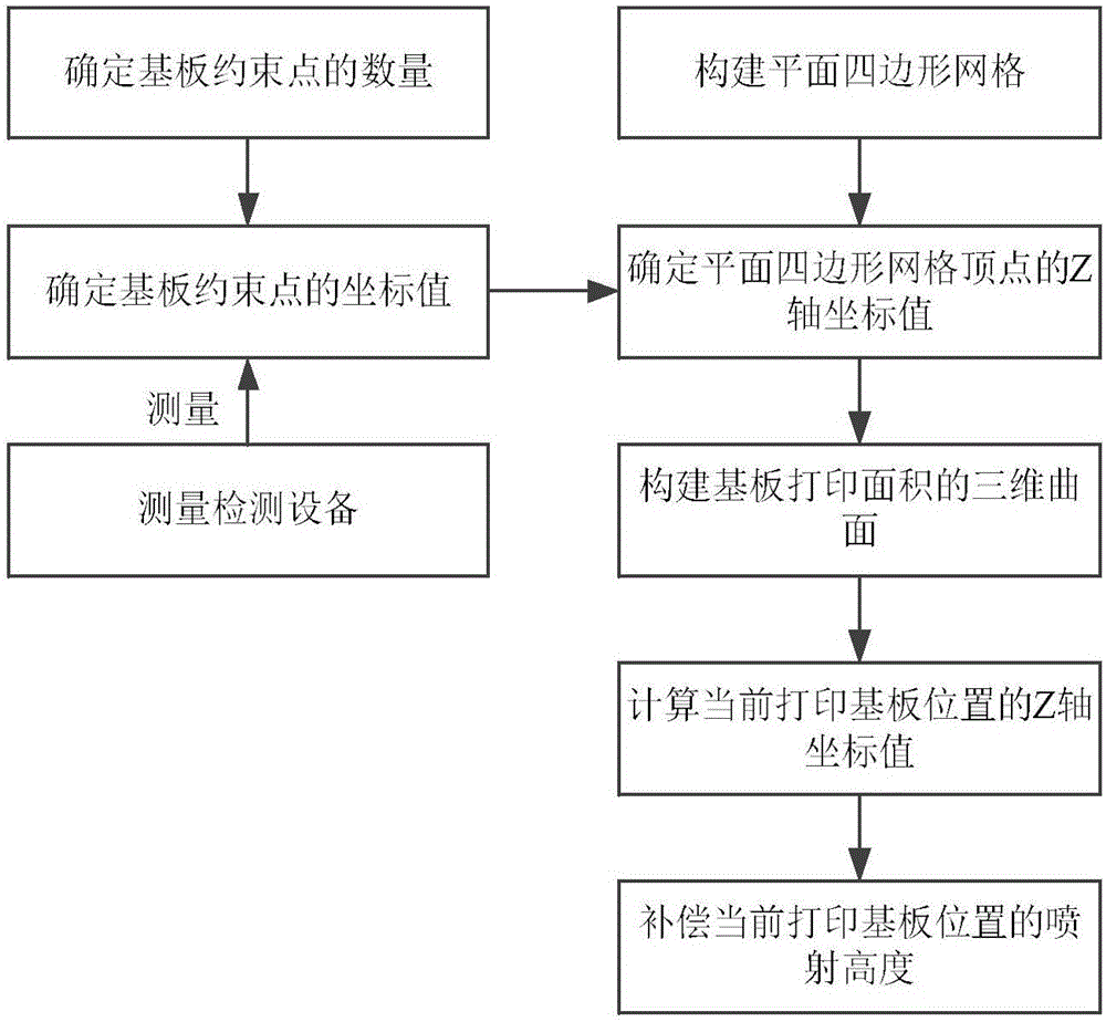
[0037] Such as figure 1 As shown, a jet height error compensation method for electrohydrodynamic printing of large-area micro-nanostructures includes the following steps:

[0038] 1. Determine the number of substrate constraint points.

[0039]According to the electrohydrodynamic printing area, determine the number of constraint points, determine the number of constraint points on the X-axis and Y-axis in the XY plane of the substrate as N and M, generally N≥3, M≥3, the larger the printing area , the larger the value of N and M, the number of constraint points is N×M, and the X-axis and Y-axis positions of each constraint point are obtained according to the moving distance of the motion platform of the electrohydrodynamic device, and the N×M The coordinates of a constraint point on the XY plane are (x i ,y i ) N×M , where 1≤i≤N×M.

[0040] 2. Determi...


PUM


Abstract

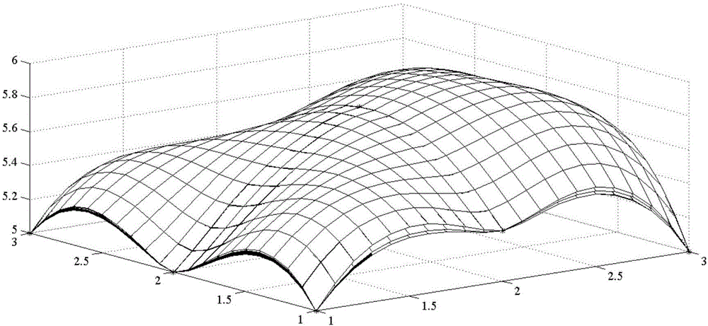
The invention discloses a jetting height error compensation method for large-area micro-nano structure electrohydrodynamics printing. The jetting height error compensation method comprises the following steps that (1) the number of constrained points of a base plate is determined; (2) the coordinate value z of the Z axis of the constrained points of the base plate is obtained; (3) a quadrilateral mesh of an XY plane is built; (4) the coordinate value z<j> of the Z axis of the vertex of the quadrilateral mesh of the XY plane is determined; (5) a three-dimensional curved surface of the printing area of the base plate is built; (6) the coordinate value z<c> of the Z axis of the current position of the printing base plate is obtained; and (7) the jetting height of electrohydrodynamics printing is compensated. According to the jetting height error compensation method for large-area micro-nano structure electrohydrodynamics printing, limitation of the existing electrohydrodynamics printing technology to precise forming of a device of a large-area micro-nano structure is broken through, and ink-jet printing of a micro-nano device of a large-area structure and preparation of a device of a micro-nano structure are achieved.

Description

technical field [0001] The invention relates to the technical field of electrohydrodynamic printing, in particular to a jet height error compensation method for electrohydrodynamic printing of large-area micro-nano structures. Background technique [0002] Electrohydrodynamic printing has broad application prospects in electronic devices, wearable devices, flexible electronic displays, solar thin-film batteries, biological scaffolds, tissue engineering, organic light-emitting diodes, and biosensors. The traditional polymer device preparation technology generally uses light, particle, mechanical or physical contact technology to prepare polymer devices on various substrates, such as photolithographic printing technology, electron beam printing technology, interference lithography technology, laser direct write etc. These preparation technologies involve many steps and complex processes, resulting in high development and production costs, and a long time period, requiring hig...

Claims


Application Information

Patent Timeline
IPC IPC(8): B41J2/07
CPCB41J2/07
Inventor 张礼兵黄风立于影左春柽吴婷
Owner JIAXING UNIV
Learn More