


Quick Research
Generate reliable direction feasibility study reports for your R&D in just a few steps.

Technical Q&A
Discover and master advanced knowledge NOW. Basics, ideas, possibilities, all at once.

Find Solutions
As an expert in R&D theories, this can generate solutions to your technical problems instantly.

Evaluate Feasibility
Analyze your overall solution with one click, know your potential R&D risks in advance.

Monitor Landscape
Get weekly tech updates, stay abreast of the latest tech innovations and key insights.
Preparation method of co-extruded plastic films different in melting point and special die head
A technology with different melting points of plastic films, which is applied in the field of dies for making co-extruded films, can solve problems such as unstable shapes and affecting product quality, and achieve the effects of ensuring stable shape, eliminating adverse effects, and improving product quality
- Summary
- Abstract
- Description
- Claims
- Application Information
AI Technical Summary
Problems solved by technology
Method used
Image


Examples
Embodiment 1
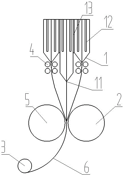
[0023] Example 1, as figure 2 As shown, the die head is divided into three layers to become three sub-die heads, which are arranged in the order of forming the film. Each sub-die head has a heating rod 12, a temperature control system, a die lip, a feeding device, etc. Separately controlled, the sub-die head of EVA in the middle has a heating temperature of 120°C, the sub-die head of PP on both sides has a heating temperature of 200°C, and the sub-die head of different temperatures has an insulating layer 13 between the layers. The heat insulating layer 13 is made of high temperature resistant tetrafluoroethylene or other high temperature resistant insulating materials. The distance between the die lip of the die of the high melting point material (PP) and the driven rubber roller is greater than the distance between the die lip 11 of the low temperature material (EVA) and the driven rubber roller, and the high melting point material is extruded first. Cool down, so as to en...
Embodiment 2
[0024] Example 2, as image 3 As shown, in Example 1, when the first extrusion design cannot reach the same or similar temperature during extrusion, there are cooling devices 4 on both sides below the die lip of the high melting point material die. By forced cooling, it is ensured that the temperature of various materials is the same or similar when they reach the active cooling roller and the driven rubber roller for extrusion. The rest of the unmentioned parts are the same as in Example 1.
Embodiment 3
[0025] Example 3, as Figure 4 As shown, the outlet of each die is the same, and the two sides below the die lip of the die of high melting point material are provided with cooling devices 4 . By forced cooling, it is ensured that the temperature of various materials is the same or similar when they reach the active cooling roller and the driven rubber roller for extrusion. The rest of the unmentioned parts are the same as in Example 1.
PUM
| Property | Measurement | Unit |
|---|---|---|
| melting point | aaaaa | aaaaa |
| melting point | aaaaa | aaaaa |
Abstract
Description
Claims
Application Information
 - R&D Engineer
- R&D Manager
- IP Professional
- Industry Leading Data Capabilities
- Powerful AI technology
- Patent DNA Extraction
Browse by: Latest US Patents, China's latest patents, Technical Efficacy Thesaurus, Application Domain, Technology Topic, Popular Technical Reports.
© 2024 PatSnap. All rights reserved.Legal|Privacy policy|Modern Slavery Act Transparency Statement|Sitemap|About US| Contact US: help@patsnap.com