
Skipping type automatic conveying device for armature shafts

A technology of automatic conveying device and armature shaft, which is applied in the direction of grinding feed motion, grinding machine parts, metal processing equipment, etc. and other problems, to achieve the effect of improving polishing processing accuracy, uniform feed rate, and reducing abnormal noise.

Inactive Publication Date: 2017-01-04
林佳一
View PDF4 Cites 2 Cited by
  • Summary
  • Abstract
  • Description
  • Claims
  • Application Information

AI Technical Summary

Problems solved by technology

Since the tooth profile on the armature shaft worm has a helical angle, this parallel clamping method will cause the worm tooth profile to have a large polishing angle on one side and a small polishing angle on the other side, resulting in asymmetrical polishing treatment of the armature shaft worm tooth profile
And the feed rate of the polishing wheel is manually controlled, and each feed rate is purely based on experience, resulting in inconsistency, and the polishing effect of the armature shaft worm is difficult to control
Finally, the motor after assembly is abnormal and noisy

Method used


Image

  • Skipping type automatic conveying device for armature shafts
  • Skipping type automatic conveying device for armature shafts
  • Skipping type automatic conveying device for armature shafts

Examples


Embodiment Construction

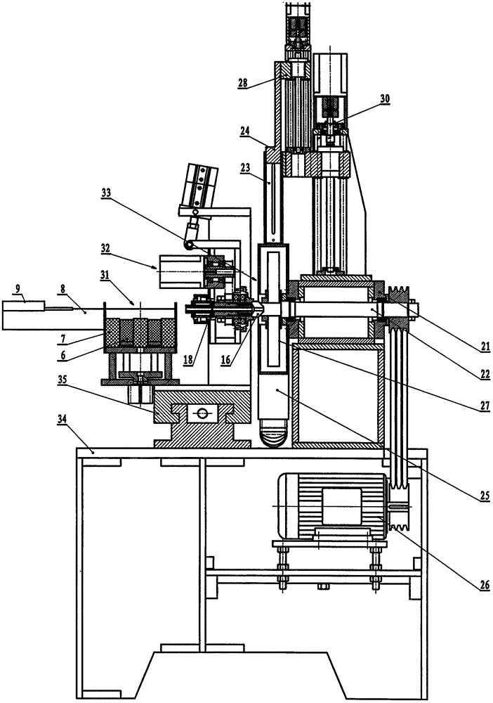
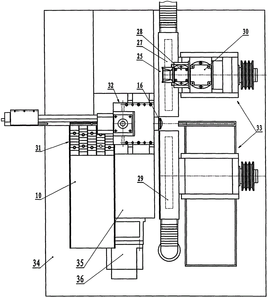
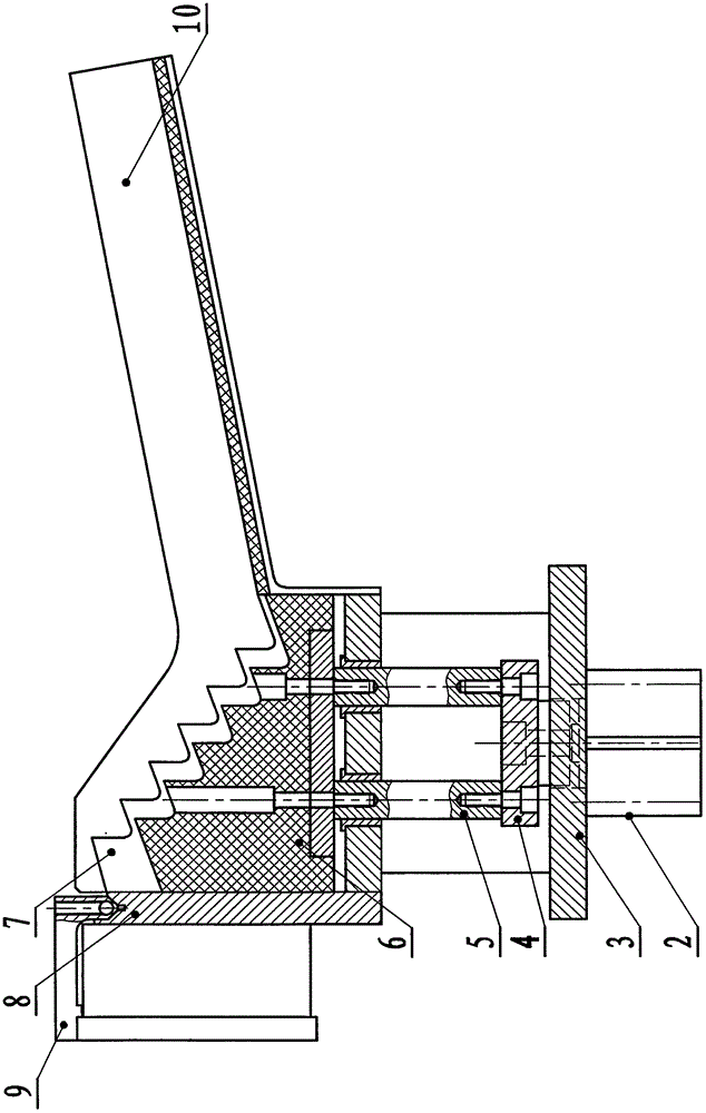
[0014] refer to image 3 , Figure 4 It can be seen that the jumping type armature shaft automatic conveying device of the present invention includes a material box 10 (with a certain slope) and a feeding bracket 3, and the material box 10 is connected with the fixed step 7 (and is fixed on the feeding bracket 3). The feeding power source 2 (feeding cylinder) is housed on the feeding support 3, and the feeding power source 2 links to each other with the feeding push plate 5 through the feeding connector 4, on the described feeding push plate 5, and with the ( In the middle) a movable step 6 is installed at the corresponding place, and a pusher block 9 is installed on the top of the step of the fixed step 7 through a material positioning plate 8 (with a groove for placing the armature shaft). 1 (for pushing material cylinder, it can be contained on the material positioning plate 8) links to each other.

[0015] Such as Figure 1 to Figure 6 , the armature shaft automatic fee...


PUM


Abstract

The invention discloses a skipping type automatic conveying device for armature shafts. The skipping type automatic conveying device comprises a material box (10) and a feeding support (3). The material box is connected with fixed steps (7), a feeding power source (2) is arranged on the feeding support (3) and connected with a feeding pushing plate (5), movable steps (6) are arranged at the positions, corresponding to the fixed steps, of the feeding pushing plate, and a pushing block (9) is arranged at the top end of the fixed steps through a material positioning plate (8) and connected with a pushing power source (1). The feeding support is arranged on a feed sliding table, and the feed sliding table is connected with a sliding table power source. By means of the skipping type automatic conveying device, the armature shaft at the lowermost stage can be conveyed upwards step by step in a one-stage skipping mode along the fixed steps to arrive at the material positioning plate finally and then is automatically conveyed out through the pushing block, labor cost is reduced, the machining precision of a worm part of the armature shaft can be improved for an armature shaft polishing device, and abnormal sounds generated when a motor works can be reduced.

Description

technical field [0001] The invention relates to an armature shaft processing equipment for a motor, in particular to an armature shaft conveying device. Background technique [0002] At present, micromotors are widely used in fields such as automobiles and home appliances, and the armature shaft (the outer end of which is designed as a worm) is an important component of the micromotor. After the worm tooth-shaped part on the end of the armature shaft is processed, the burrs need to be removed by means of buffing wheel polishing, so as to achieve the matching precision with the gear (worm wheel). The known armature shaft is manually conveyed, and the polishing method of the armature shaft is that the worm part of the armature shaft is clamped in parallel with the polishing wheel, and the armature shaft clamping motor and the polishing motor respectively drive the armature shaft and the polishing wheel to rotate in the opposite direction And contact achieves polishing. Becau...

Claims


Application Information

Patent Timeline
Patent Type & Authority Applications(China)
IPC IPC(8): B24B41/00
CPCB24B41/005
Inventor 林佳一
Owner 林佳一
Learn More