A laser drilling steel plate clamping mechanism

A clamping mechanism and laser drilling technology, which is applied in laser welding equipment, welding equipment, metal processing equipment, etc., can solve the problems of unevenness on the board surface, low accuracy of drilling position, and influence on processing effect, etc., to achieve guaranteed The effect of the drilling effect

Active Publication Date: 2018-05-11
江苏九九铝业有限公司
View PDF12 Cites 0 Cited by
  • Summary
  • Abstract
  • Description
  • Claims
  • Application Information

AI Technical Summary

Problems solved by technology

[0003] The thin steel plate needs to be clamped and fixed when drilling, and the thin steel plate will cause the problem of unevenness and unevenness on the surface of the plate when it is transported. After clamping and fixing, when drilling, the accuracy of the drilling position Not high, affect the processing effect

Method used


Image

  • A laser drilling steel plate clamping mechanism
  • A laser drilling steel plate clamping mechanism

Examples


Embodiment Construction

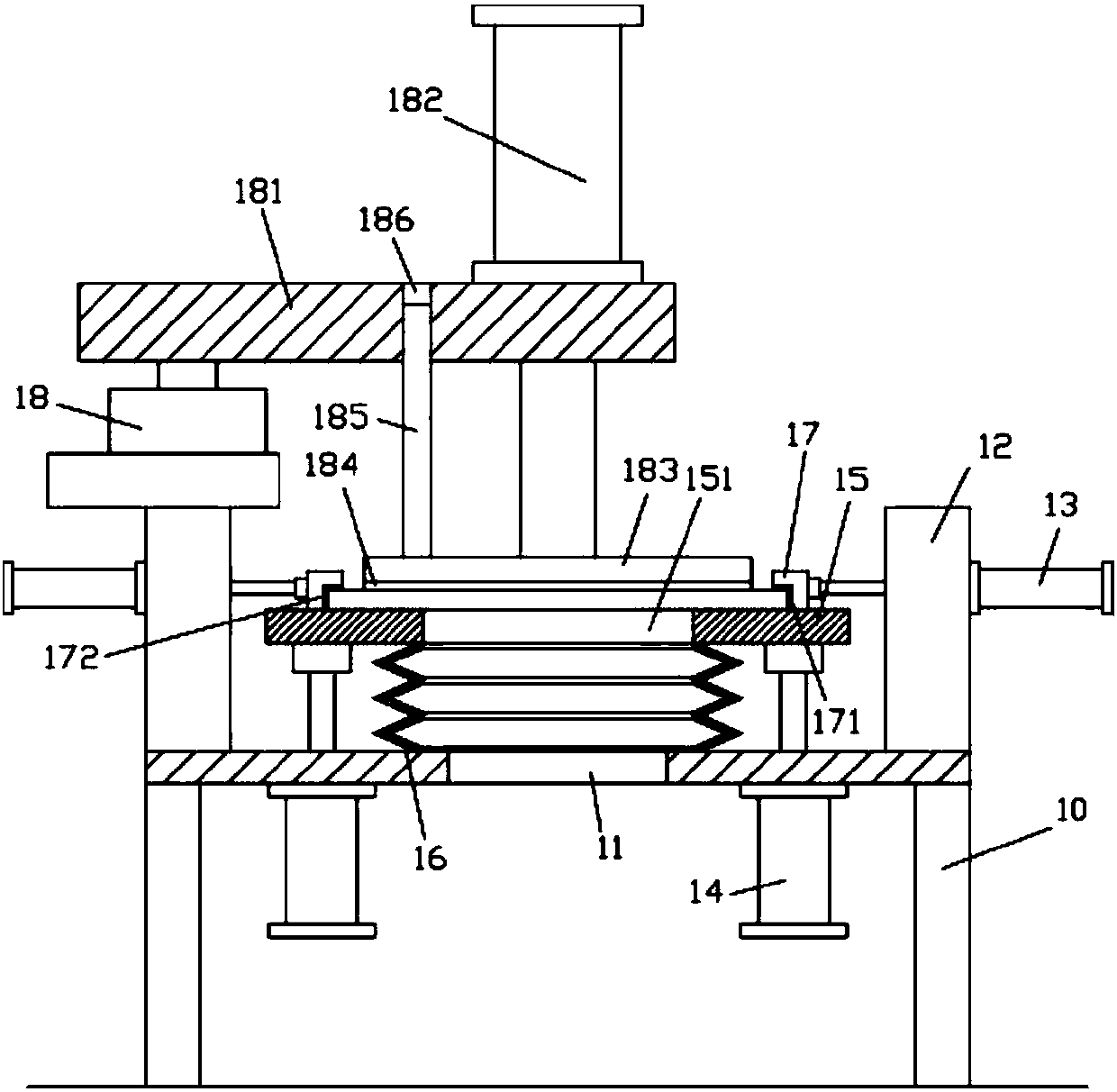
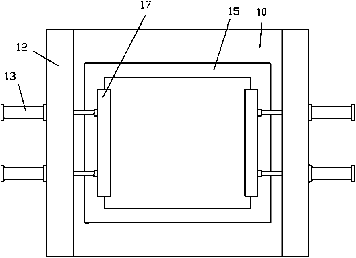
[0017] Examples, see e.g. Figure 1 to Figure 2 As shown, a laser drilling steel plate clamping mechanism includes a frame 10, the middle part of the top plate of the frame 10 has a discharge through hole 11, and the left and right top surfaces of the top plate of the frame 10 are fixed with vertical Support plate 12, a plurality of clamping cylinders 13 are fixed on the outer wall of the vertical support plate 12, lifting cylinders 14 are fixed on both sides of the bottom surface of the top plate of the frame 10, and the push rod of the lifting cylinder 14 passes through the frame vertically upwards 10 and is fixed on the bottom surface of the support plate 15, the support plate 15 is above the top plate of the frame 10, the middle part of the support plate 15 has a blanking through hole 151, and the blanking through hole 151 is aligned with the discharge through hole 11 up and down , the upper end of the corrugated protective cover 16 is fixed on the bottom surface of the su...


PUM


Abstract

The invention discloses a laser drilling clamping mechanism for a steel plate. The laser drilling clamping mechanism comprises a rack, wherein a material discharging through hole is formed in the middle part of a top plate of the rack; vertical supporting plates are fixed on the top surfaces of the left side and the right side of the top plate of the rack; a plurality of clamping cylinders are fixed on the outer side walls of the vertical supporting plates; lifting cylinders are fixed on two sides of the bottom surface of the top plate of the rack; push rods of the lifting cylinders vertically and upwards penetrate through the top plate of the rack and are fixed on the bottom surface of a supporting plates; the supporting plate is located above the top plate of the rack; a material blanking through hole is formed in the middle part of the supporting plate and is flush with a material discharging through hole up and down; the upper end of a corrugated protection sleeve is fixed on the bottom surface of the supporting plate; the lower end of the corrugated protection sleeve is fixed on the top plate of the rack; the upper end of the corrugated protection sleeve is connected with the material blanking through hole; the lower end of the corrugated protection sleeve is connected with the material discharging through hole. The laser drilling clamping mechanism can enable the thin steel plate to be flattened and firmly clamp the steel plate to guarantee the subsequent drilling effect.

Description

Technical field: [0001] The invention relates to the technical field of laser processing equipment, in particular to a laser drilling steel plate clamping mechanism. Background technique: [0002] Laser drilling is the use of high-power-density laser beams to irradiate the processed material, so that the material is quickly heated to the vaporization temperature, and evaporates to form holes. Laser drilling is the earliest practical laser processing technology, and it is also one of the main application fields of laser processing. [0003] The thin steel plate needs to be clamped and fixed when drilling, and the thin steel plate will cause the problem of unevenness and unevenness on the surface of the plate when it is transported. After clamping and fixing, when drilling, the accuracy of the drilling position Not high, affecting the processing effect. Invention content: [0004] The purpose of the present invention is to overcome the deficiencies of the prior art, and pr...

Claims


Application Information

Patent Timeline
Patent Type & Authority Patents(China)
IPC IPC(8): B23K26/70B23K26/382
CPCB23K26/382B23K26/702
Inventor 李风浪李舒歆
Owner 江苏九九铝业有限公司
Why Eureka
Try Eureka