
Tool for forming convex-concave multi-curvature type airplane skin product and composite forming technology

An aircraft skin and multi-curvature technology, which is applied in the field of sheet metal forming and manufacturing, can solve the problems of affecting the overall strength and rigidity of the part, increasing the difficulty of part positioning, and the inability to use the Mengla process, so as to reduce the number of divisions, Guaranteeing integrity and reducing production costs

Active Publication Date: 2017-01-04
天津天锻航空科技有限公司
View PDF7 Cites 15 Cited by
  • Summary
  • Abstract
  • Description
  • Claims
  • Application Information

AI Technical Summary

Problems solved by technology

Convex-concave and multi-curvature skin parts made by traditional forming methods have poorer structural integrity than those processed through composite forming, which affects the overall strength and stiffness of the parts; at the same time, additional connecting frames are required, which increases the The positioning of the parts is difficult, the production efficiency is low, and unnecessary man-hours such as manual installation are required
[0005] When processing convex-convex multi-curvature aircraft skin products 7 (such as Figure 7 As shown), because the part has convex-concave and multi-curvature features, it cannot be formed by the Mongolian drawing process, nor can it be formed by adding an upper die during the Mongolian drawing process
At this time, liquid-filled forming technology will be considered to form the part, but if only a large forming pressure is required to form the ridge feature through the liquid-filled forming process, it will require a large tonnage of hydraulic equipment, and the problem of springback It will also be more prominent, and even prone to wrinkles and other defects during the ridge forming process

Method used


Image

  • Tool for forming convex-concave multi-curvature type airplane skin product and composite forming technology
  • Tool for forming convex-concave multi-curvature type airplane skin product and composite forming technology
  • Tool for forming convex-concave multi-curvature type airplane skin product and composite forming technology

Examples


Embodiment Construction

[0039] In order to further understand the invention content, characteristics and effects of the present invention, the following examples are given, and detailed descriptions are as follows in conjunction with the accompanying drawings:

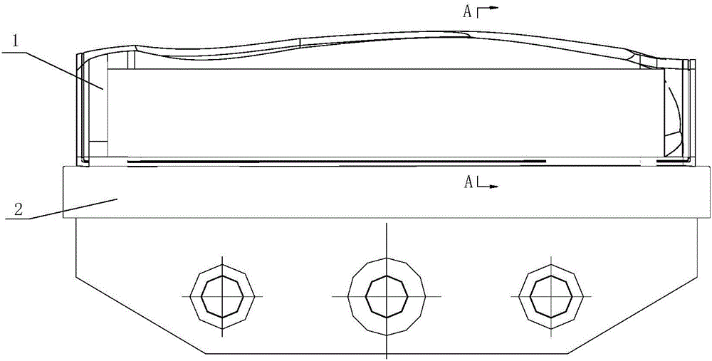
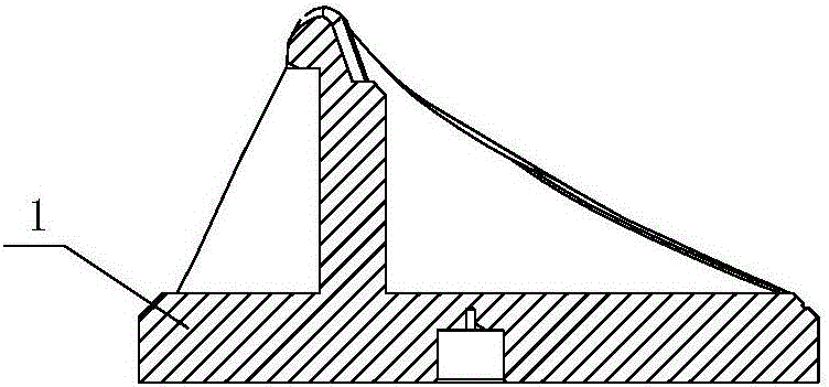
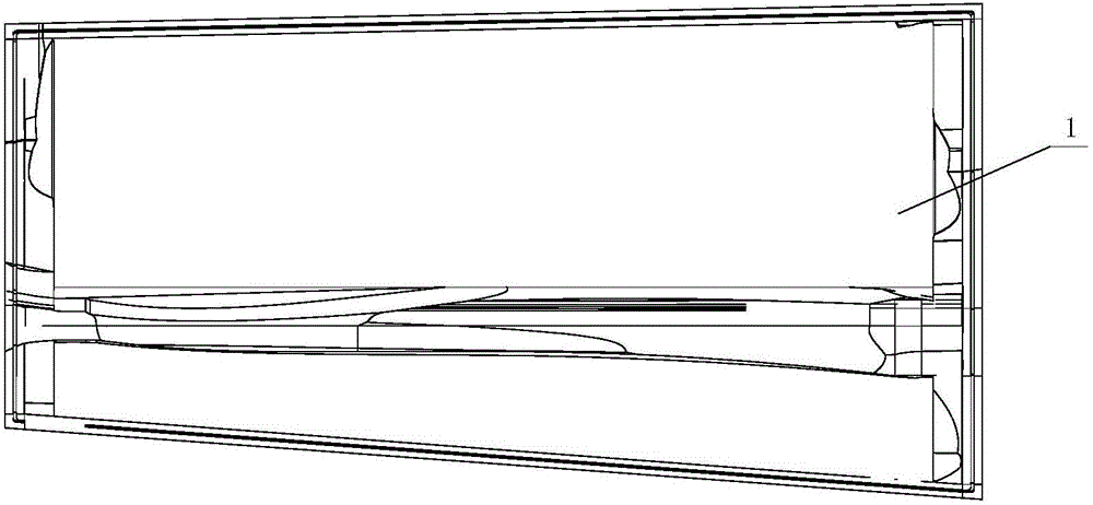
[0040] see Figure 1-Figure 6 , a tooling for forming convex-concave multi-curvature aircraft skin parts, comprising an upper template 3, a punch 1, a die 6 and a sealing ring 9, the die cavity is shaped like an inverted herringbone, and the screw It is connected with the upper template, and is guided and positioned with the upper template by the guide sleeve 4 and the guide pin 5, and the guide pin 5 and the die 6 are transition fit. The punch is composed of a pressing plate and a vertical rib integrated with the pressing plate. The head of the vertical rib of the punch is formed with a profile that matches the ridge of the product. It is fixed on the workbench 2 of the Mengla mold by fasteners to prevent the punch 1 from jumping during the...


PUM


Abstract

The invention relates to a tool for forming a convex-concave multi-curvature type airplane skin product and a composite forming technology. The tool comprises an upper die plate, a male die, a female die and a sealing ring. An inverted-herringbone-shaped die cavity is formed in the female die and connected with the upper die plate. The male die comprises a press plate and a vertical rib, wherein a profile which coincides with the ridge portion of the product is manufactured on the head of the vertical rib. The male die is arranged in the die cavity of the female die and fixedly connected with the upper die plate, and the sealing ring is arranged on the portion of contact between the press plate of the male die and the female die. The forming technology comprises the steps that skin stretching forming is conducted by a skin stretching facility on a plate material, and hydraulic forming is conducted on the product through a hydraulic bulging machine. The tool for forming the convex-concave multi-curvature type airplane skin product and the composite forming technology have the advantages that the forming accuracy of the product can be improved, the integrity of skin parts is guaranteed, the division number is reduced, the integral strength and the integral rigidity of the product are enhanced, the technology of the convex-concave multi-curvature type airplane skin product is simplified, the manufacturing difficulty is reduced, the production efficiency is effectively improved, the production cost is substantially reduced, and the tool and the composite forming technology can be widely applied to the industrial fields such as the aerospace field and the automobile field.

Description

technical field [0001] The invention belongs to the technical field of forming and manufacturing sheet metal parts, in particular to a tooling for forming convex-concave multi-curvature aircraft skin parts and a composite forming process. Background technique [0002] Skin stretch forming is a typical sheet forming method in the field of aviation manufacturing. It is mainly used to produce large-scale skin parts that constitute the aerodynamic shape of the aircraft. The process is as follows: first clamp the sheet with clamps located on both sides of the sheet, Then, through the cladding stretching movement of the clamps or the vertical upward lifting movement of the drawing mold, the sheet is gradually attached to the surface of the drawing mold and stretched and deformed to obtain the final shape. The characteristic of the drawing process is to add tangential tension while the plate is bending, so that the stress in the section of the plate tends to be uniform and reduce t...

Claims


Application Information

Patent Timeline
IPC IPC(8): B21D35/00B21D37/10B21D22/22B21D26/031
CPCB21D22/22B21D26/031B21D35/002B21D37/10
Inventor 张建民陈树来张淳郎利辉张艳峰孙钢桑悦诚
Owner 天津天锻航空科技有限公司
Learn More